- Catalogs
- Shenzhen Hongguang Display Co., Ltd
- HGYD2690H-V1
- Company
- Products
- Catalogs
- News & Trends
- Exhibitions
HGYD2690H-V1
1 /21Pages

HGYD2690H-V1
1 /21Pages
Catalog excerpts

Approved by/核准
Open the catalog to page 1
HGYD2690H-V1 User Manual Contents
Open the catalog to page 3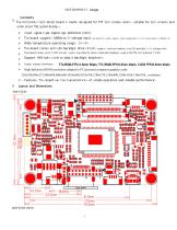
Contents The HGYD2690H-V1LCD driver board is mainly designed for TFT LCD screens and is suitable for LCD screens and some other flat panel displays. Input signal type: Digital high definition (HDMI). The board supports USBMicro 5V voltage input Wide temperature operating range: -20~+80 The board comes with LED backlight drive circuit; The board comes with T-CON circuit, which can directly drive small and medium-sized LVDS/TTL LCD without T-CON Support PWM duty cycle to adjust backlight brightness Display output interface:: High-definition HDMI resolutions adapted to PC (personal computer) graphics...
Open the catalog to page 4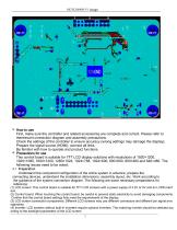
First, make sure the controller and related accessories are complete and correct. Please refer to therelevant connection diagram and assembly precautions. Check the settings of the controller to ensure accuracy (wrong settings may damage the display); Prepare the signal source (HDMI); connect all links. Be familiar with how to operate and product functions. 4. Precautions for use This control board is suitable for TFT LCD display solutions with resolutions of 1920×1200, 1920×1080, 1600×1200, 1280×1024, 1024×768, 1024×600, 800×600, 800×480 and 640×480. The following issues need to be noted: 4.1...
Open the catalog to page 5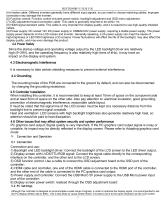
HGYD2690H-V1 使用手册 (5) Inverter cable: Different inverters generally have different input signals, so you need to choose matching cables. Improper connection may damage the inverter. (6) Function control: Function control includes power switch, backlight adjustment and OSD menu adjustment. (7) OSD adjustment board connection cable: This cable is generally required to be within 1m. (8) HDMI signal standard cable: This cable is very important for display quality, and it is required to use high-quality shielded cables. (9) Power supply: DC socket 12V DC power supply or USBMicro5V power supply, requiring...
Open the catalog to page 6
5.3 Adjustment Operation After the system is connected and working properly, it can be adjusted through the OSD menu. After the adjustment, the parameters will be automatically stored after exiting the menu. 5.4 Display system block diagram Please see the figure on the next page: Description: 1. TFT LCD screen; 2. Display controller: HGYD2690H-V1 3. OSD (On Screen Display) function adjustment board (manufacturers can make their own OSD keypad according to the definition); 4. Cable connecting the LCD screen to the control board; 5. Cable connecting the OSD adjustment board to the control boar
Open the catalog to page 7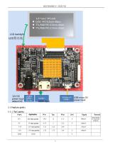
12V DC power input default NC USB micro 5V power input HDMI input 5.5 Feature points 5.5.1 Test points Mark Remark Determined by external mo
Open the catalog to page 8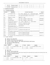
Backlight Enable 5.6 Interface Description 5.6.1 Interface Overview Interface Connector Description Appplication 12V DC power input 4P, 2.0Pitch, single row, 180°, socket (JST/CVILUX) DCJACK, positive inside and negative outside, positive pole outer diameter φ2. HDMI input HDMI-19pin, 90 degrees, Taiwan socket HDMI input Mini HDMI input HDMI-19pin, 90 degrees, Taiwan socket OSD adjustment keyboard and infrared control interface 12P, 1.25Pitch, single row, 90°, socket (molex) Backlight power supply and control interface output 0mm, negative pole inner diameter φ5.5mm (JST/CVILUX) LED backlight...
Open the catalog to page 9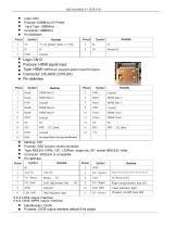
Logo: CN3 Purpose: USBMicro 5V Power Input Type: USBMicro Connector: USBMicro Pin Definition Logo: CN12 Purpose: HDMI signal input Type: HDMI-19PIN/4-pin plug/gold-plated copper/90-degree Connector: DCJACK (CVILUX) Pin definition Symbol HDMI Clock - HDMI Clock+ Hot plug Detect hot plug identification Marking: CN7 Purpose: OSD function control connector Type: MOLEX-12PIN, 12P, 1.25Pitch, single row, 90°, socket (MOLEX), white Connector: (MOLEX) or compatible Pin definition Symbol Signal source selection shortcut key/exit key K1 Green indicator light 5.6.3 LVDS output interface 5.6.5 LVDS-40PIN...
Open the catalog to page 10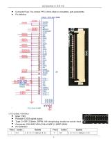
Connector/Type: Top contact, FFC-0.5mm-40pin or compatible, gold-plated/white Pin definition LVDS output interface Mark: CN5 Purpose: LVDS signal output Type: 2×10P, 2.0pitch, 20PIN, 180° straight plug, double-row socket, black Connector: CI0130P1VD0 (CVILUX)/DF11-30DP-2DSA Pinout 1
Open the catalog to page 11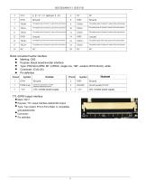
The negative pole of channel 1 output of the odd channel. The positive pole of channel 1 output of the odd channel. The negative pole of channel 2 output of the odd channel. The positive pole of channel 2 output of the odd channel. The negative pole of channel 3 output of the odd channel. The positive pole of channel 3 output of the odd channel. The negative pole of the clock output of the odd channel. The positive pole of the clock output of the odd channel. The negative pole of channel 4 output of the odd channel. The positive pole of channel 4 output of the odd channel. Boost converter/inverter...
Open the catalog to page 12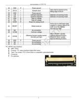
TTL-40PIN output interface Mark: CN18 Purpose: TTL output interface default 8bit output Type: Top contact, FFC-0.5mm-40pin or compatible, gold-plated/white Connector: Pin
Open the catalog to page 14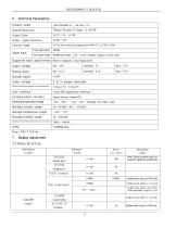
Technical Parameters Product model Overall dimensions Display Color Display screen interface Control range LCD with resolutions ranging from 480×272 to 1920×1200 Signal input Input signal type Input signal range HDMIInput range Supported input signal formats Refer to Appendix A and Appendix B Supply voltage Working current Standby power Display voltage Maximum display load capacity (normal temperature) User Interface Visual OSD operation interface Communication Interface Digital buttons, infrared IR Working temperature range Working humidity range Storage temperature range Storage humidity range...
Open the catalog to page 16
垂直位置(V Position) Visible when input is VGA only 水平位置(H Position) 垂直位置(V Position) 时间(OSD Timeout) Menu disappearance time setting when no operation is performed When 7 is selected, the transparency is the highest. When Off is selected, the transparency is 0. Visible when input is VGA only Visible when input is VGA only 显示比例(Display Ratio) 蓝屏(Blue Screen) Image flip up, down, left, right (need to confirm whether the screen supports it) 7.2 Operation Instructions 7.2.1 Button Instructions: Digital button description K1(Source/EXIT) Signal source input selection key/exit key Main menu button, confirm...
Open the catalog to page 17All Shenzhen Hongguang Display Co., Ltd catalogs and technical brochures
 HG215FH008T01
30 Pages
 HG185FH005
21 Pages
 HG170SX006T01
20 Pages
 HG160WQ004
64 Pages
 HG156FH011
23 Pages
 HG133FH017T01
32 Pages
 HG121WX001T01
22 Pages
 HG116FH008
24 Pages
 HG104SV003
27 Pages
 HG101WX054
12 Pages
 HG101WX053
12 Pages
 HG101WX049
38 Pages
 HG101WX047T01
19 Pages
 HG101WX047
19 Pages
 HG101WX046
18 Pages
 HG101WX030
24 Pages
 HG101WX028
21 Pages
 HG101WX026T01
20 Pages
 HG101WX025
19 Pages
 HG101WX022
19 Pages
 HG101WX021T01
20 Pages
 HG101WX021
20 Pages
 HG050WV038
18 Pages
 HG101WX019T01
20 Pages
 HG101WX019
20 Pages
 HG101WX016
20 Pages
 HG101WX005T01
22 Pages
 HG101WU076
25 Pages
 HG101WU072T01
23 Pages
 HG101WU072
23 Pages
 HG101WU065
23 Pages
 HG101WU063
24 Pages
 HG101WU062
27 Pages
 HG101WU039
30 Pages
 HG101WU035
23 Pages
 HG101WU032T01
18 Pages
 HG101WU013
17 Pages
 HG101WU010
17 Pages
 HG101WU008T01
17 Pages
 HG101WS045
22 Pages
 HG101WS042
17 Pages
 HG101WS040
19 Pages
 HG101WQ004T01
13 Pages
 HG101WQ003
13 Pages
 HG097XG006T01
17 Pages
 HG097QX005
17 Pages
 HG097QX003Z05
18 Pages
 HG097QX003T02
18 Pages
 HG097QX003T01
18 Pages
 HG090WS008
19 Pages
 HG080WX034
19 Pages
 HG080WX032
12 Pages
 HG080WX015
19 Pages
 HG080WX013
19 Pages
 HG080WV029
20 Pages
 HG080WV027
22 Pages
 HG080WU018T01
19 Pages
 HG080WU009
14 Pages
 HG070WX006
13 Pages
 HG070WX005
19 Pages
 HG070WS051T01
19 Pages
 HG070WV048
23 Pages
 HG070WV047
23 Pages
 HG070WV037R01
20 Pages
 HG070WV035T01
19 Pages
 HG070WV035
18 Pages
 HG070WV031
12 Pages
 HG070WV026
23 Pages
 HG070WV022
23 Pages
 HG070WV020
12 Pages
 HG070WV013T01
20 Pages
 HG070WV013R02
20 Pages
 HG070WU039
25 Pages
 HG070WS055
14 Pages
 HG070WS052
13 Pages
 HG070WV051T01
19 Pages
 HG070WS050
22 Pages
 HG070WS049T02
13 Pages
 HG070WS049T01
13 Pages
 HG070WS049-V1
21 Pages
 HG070WS048
25 Pages
 HG070WS046T03
13 Pages
 HG050HD030-V3
18 Pages
 HG215FH008T02
30 Pages
 HG104SV004
21 Pages
 HG050HD030T01
18 Pages
Archived catalogs
 HG043HV026
16 Pages
 HG024QV023R01
1 Page
 HG030FH006T02
16 Pages
 HG055FH018T01
20 Pages
 HG055HD017
16 Pages
 HG055FH021
20 Pages
 HG005WS003
39 Pages
 HG007WS003
50 Pages
 HG010WZ003
50 Pages
 HG015WZ003
49 Pages
 HG080STD02C
7 Pages
 HG104VG002-V0
20 Pages
 HG215FH008
30 Pages
 HG097XG008
17 Pages
 HG173FH002G01
30 Pages
 HG173FH002
30 Pages
 HG043HV002T02
17 Pages
 HG050WV009
19 Pages
 HG028HS003
15 Pages
 HG032WV001
17 Pages
 HG032XG003
19 Pages
 HG034SV004
14 Pages
 HG035SV003
22 Pages
 HG039WV004
19 Pages
 HG040HH005
16 Pages
 HG040HS002T01
16 Pages
 HG040WV006T02
18 Pages
 HG043HV002P01
10 Pages
 HG043HV002R03
17 Pages
 HG043WV005T01
19 Pages
 HG140FH005
20 Pages
 HG043HV008
17 Pages
 HG043HV008T01
17 Pages
 HG043HV009
21 Pages
 HG043HV010
21 Pages
 HG050WV010
19 Pages
 HG030FW006
14 Pages
 HG043HV022
16 Pages
 HG043HV028
20 Pages
 HG043WV016
18 Pages
 HG043WV023T01
19 Pages
 HG043HV029
19 Pages
 HG080WX039-V0
19 Pages
 HG050FH028T02
18 Pages
 HG050HD026T01
18 Pages
 HG101WU042-V0
29 Pages
 HG060HD012
18 Pages
 HG025HV006
12 Pages
 HG050QZ002
21 Pages
 HG050WV005
18 Pages
 HG050WV005T01
18 Pages
 HG050WV008T01
20 Pages
 HG050WV09G01
19 Pages
 HG050WV032
10 Pages
 HG050WV032T01
10 Pages
 HG050WV033
10 Pages
 HG050WV034
20 Pages
 HG055HD016T01
19 Pages
 HG062WV003
19 Pages
 HG062WV006
20 Pages
 HG064XG003
20 Pages
 HG069HS004
20 Pages
 HG070WS004T06
13 Pages
 HG070WS011
13 Pages
 HG070WS012
26 Pages
 HG070WS002
13 Pages
 HG070WS004P01
22 Pages
 HG070WS013
24 Pages
 HG070WS018
19 Pages
 HG070WS045
13 Pages
 HG070WS045T01
13 Pages
 HG070WS045T02
13 Pages
 HG070WS046T02
13 Pages

- Industrial display panel
- TFT display module
- Touch screen display panel
- Color display panel
- LED display panel
- Electronic display panel
- Control display system
- IPS display panel
- Programmable display system
- Information display
- RS-232 display panel
- Outdoor display panel
- Built-in display
- Instrumentation display panel
- Medical equipment display
- Graphic display panel
- Control panel display panel
- RGB display panel