- Company
- Products
- Catalogs
- News & Trends
- Exhibitions
HG160WQ004
1 /64Pages

HG160WQ004
1 /64Pages
Catalog excerpts
Shenzhen Hongguang Display Co.,Ltd CUSTOMER : CUSTOMER MODULE : HL MODEL Preliminary Specification ■Final Specification Customer Confirmation column: Approved by : Please return one of the copies of the specification with your signature to us within two weeks after you receive this document.If it is not returned,we will assume that you agree to the entire contents of this specification document. Hongguang Display
Open the catalog to page 1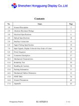
Shenzhen Hongguang Display Co.,Ltd General Description Absolute Maximum Ratings Electrical Specifications Optical Specifications Interface Connection Signal Timing Specification Input Signals, Display Colors & Gray Scale of Colors Power Sequence Connector Description Mechanical Characteristics Reliability Test Handling & Cautions Packing Information Mechanical Outline Dimension EDID Table General Precautions Hongguang Display
Open the catalog to page 2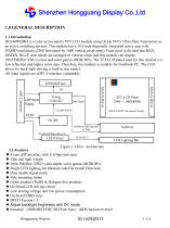
Shenzhen Hongguang Display Co.,Ltd 1.0 GENERAL DESCRIPTION 1.1 Introduction HG160WQ004 is a color active matrix TFT LCD module using Oxide TFT's (Thin Film Transistors) as an active switching devices. This module has a 16.0 inch diagonally measured active area with WQHD resolutions (2560 horizontal by 1600 vertical pixel array). Each pixel is divided into RED, GREEN, BLUE dots which are arranged in vertical stripe and this module can display 1064.3M(8bit+FRC) colors and color gamut sRGB100%. The TFT-LCD panel used for this module is a low reflection and higher color type. Therefore, this module...
Open the catalog to page 3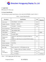
Shenzhen Hongguang Display Co.,Ltd 1.3 Application Notebook PC (Wide type) 1.4 General Specification The followings are general specifications at the model HG160WQ004. (listed in Table 1) Parameter Active area Pixel pitch Pixel arrangement Display colors Color gamut Display mode Normally Black Dimensional outline Surface treatment Surface hardness Bottom edge side, 1-LED lighting bar type Power consumption Notes : 1. LED Lighting Bar (88*LED Array) Hongguang Display
Open the catalog to page 4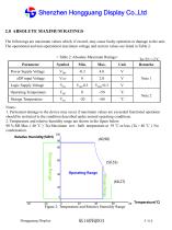
Shenzhen Hongguang Display Co.,Ltd 2.0 ABSOLUTE MAXIMUM RATINGS The followings are maximum values which, if exceed, may cause faulty operation or damage to the unit. The operational and non-operational maximum voltage and current values are listed in Table 2. < Table 2. Absolute Maximum Ratings> Parameter Power Supply Voltage Logic Supply Voltage Operating Temperature Storage Temperature Notes : 1. Permanent damage to the device may occur if maximum values are exceeded functional operation should be restricted to the condition described under normal operating conditions. 2. Temperature and relative...
Open the catalog to page 5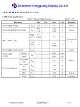
Shenzhen Hongguang Display Co.,Ltd 3.0 ELECTRICAL SPECIFICATIONS 3.1 Electrical Specifications < Table 3. Electrical Specifications > Parameter Power Supply Voltage Permissible Input Ripple Voltage BIST Control Level Power Supply Inrush Current Power Supply Current Power Consumption Hongguang Display
Open the catalog to page 6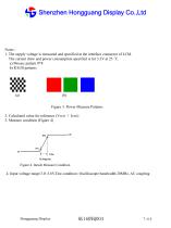
Shenzhen Hongguang Display Co.,Ltd Notes : 1. The supply voltage is measured and specified at the interface connector of LCM. The current draw and power consumption specified is for 3.3V at 25 °C. a) Mosaic pattern 8*8 b) R/G/B patterns (b) Figure 3. Power Measure Patterns 2. Calculated value for reference (VLED × ILED) 3. Measure condition (Figure 4) Figure 4. Inrush Measure Condition 4. Input voltage range:3.0~3.6V.Test condition: Oscilloscope bandwidth 20MHz, AC coupling Hongguang Display
Open the catalog to page 7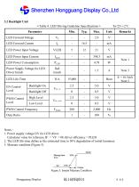
Shenzhen Hongguang Display Co.,Ltd 3.2 Backlight Unit < Table 4. LED Driving Guideline Specifications > Parameter LED Power Input Voltage LED Power Input Current Iled inrush Power Supply Voltage for LED Driver Inrush LED Life-Time EN Control Level High Level Backlight Off VBL_PWM Low Level PWM Control Frequency Duty Ratio Notes : 1. Power supply voltage12V for LED driver. Calculator value for reference IF × VF × 88 /driver efficiency = PLED 2. The LED life-time define as the estimated time to 50% degradation of initial luminous. 3. Measure condition (Figure 5) Figure 5. Inrush Measure Condition...
Open the catalog to page 8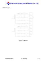
Shenzhen Hongguang Display Co.,Ltd 3.3 LED Structure Hongguang Display
Open the catalog to page 9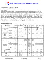
Shenzhen Hongguang Display Co.,Ltd 4.0 OPTICAL SPECIFICATION 4.1 Overview The test of optical specifications shall be measured in a dark room (ambient luminance 1 lux and temperature = 252℃) with the equipment of luminance meter system (PR730&PR810) and test unit shall be located at an approximate distance 50cm from the LCD surface at a viewing angle of θ and Φ equal to 0. We refer to θØ=0 (=θ3 ) as the 3 o’clock direction (the “right”), θØ=90 (= θ12 ) as the 12 o’clock direction (“upward”), θØ=180 (= θ9 ) as the 9 o’clock direction (“left”) and θØ=270(= θ6 ) as the 6 o’clock direction (“bottom”)....
Open the catalog to page 10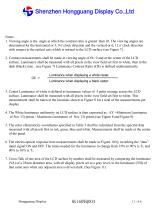
Shenzhen Hongguang Display Co.,Ltd Notes : 1. Viewing angle is the angle at which the contrast ratio is greater than 10. The viewing angles are determined for the horizontal or 3, 9 o’clock direction and the vertical or 6, 12 o’clock direction with respect to the optical axis which is normal to the LCD surface (see Figure 7). 2. Contrast measurements shall be made at viewing angle of Θ= 0 and at the center of the LCD surface. Luminance shall be measured with all pixels in the view field set first to white, then to the dark (black) state . (see Figure 7) Luminance Contrast Ratio (CR) is defined...
Open the catalog to page 11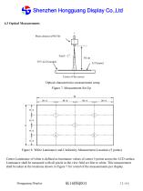
Shenzhen Hongguang Display Co.,Ltd 4.3 Optical Measurements TFT-LCD module Optical characteristics measurement setup Figure 7. Measurement Set Up Figure 8. White Luminance and Uniformity Measurement Locations (5 points) Center Luminance of white is defined as luminance values of center 5 points across the LCD surface. Luminance shall be measured with all pixels in the view field set first to white. This measurement shall be taken at the locations shown in Figure 7 for a total of the measurements per display. Hongguang Display
Open the catalog to page 12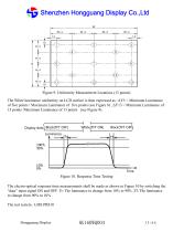
Shenzhen Hongguang Display Co.,Ltd Figure 9. Uniformity Measurement Locations (13 points) The White luminance uniformity on LCD surface is then expressed as : ΔY5 = Minimum Luminance of five points / Maximum Luminance of five points (see Figure 8) , ΔY13 = Minimum Luminance of 13 points /Maximum Luminance of 13 points (see Figure 9). Display data Black(TFT OFF) Luminance Figure 10. Response Time Testing The electro-optical response time measurements shall be made as shown in Figure 10 by switching the “data” input signal ON and OFF. Tr: The luminance to change from 10% to 90% ,Tf: The luminance...
Open the catalog to page 13All Shenzhen Hongguang Display Co., Ltd catalogs and technical brochures
 HG215FH008T01
30 Pages
 HG185FH005
21 Pages
 HG170SX006T01
20 Pages
 HG156FH011
23 Pages
 HG133FH017T01
32 Pages
 HG121WX001T01
22 Pages
 HG116FH008
24 Pages
 HG104SV003
27 Pages
 HG101WX054
12 Pages
 HG101WX053
12 Pages
 HG101WX049
38 Pages
 HG101WX047T01
19 Pages
 HG101WX047
19 Pages
 HG101WX046
18 Pages
 HG101WX030
24 Pages
 HG101WX028
21 Pages
 HG101WX026T01
20 Pages
 HG101WX025
19 Pages
 HG101WX022
19 Pages
 HG101WX021T01
20 Pages
 HG101WX021
20 Pages
 HG050WV038
18 Pages
 HG101WX019T01
20 Pages
 HG101WX019
20 Pages
 HG101WX016
20 Pages
 HG101WX005T01
22 Pages
 HG101WU076
25 Pages
 HG101WU072T01
23 Pages
 HG101WU072
23 Pages
 HG101WU065
23 Pages
 HG101WU063
24 Pages
 HG101WU062
27 Pages
 HG101WU039
30 Pages
 HG101WU035
23 Pages
 HG101WU032T01
18 Pages
 HG101WU013
17 Pages
 HG101WU010
17 Pages
 HG101WU008T01
17 Pages
 HG101WS045
22 Pages
 HG101WS042
17 Pages
 HG101WS040
19 Pages
 HG101WQ004T01
13 Pages
 HG101WQ003
13 Pages
 HG097XG006T01
17 Pages
 HG097QX005
17 Pages
 HG097QX003Z05
18 Pages
 HG097QX003T02
18 Pages
 HG097QX003T01
18 Pages
 HG090WS008
19 Pages
 HG080WX034
19 Pages
 HG080WX032
12 Pages
 HG080WX015
19 Pages
 HG080WX013
19 Pages
 HG080WV029
20 Pages
 HG080WV027
22 Pages
 HG080WU018T01
19 Pages
 HG080WU009
14 Pages
 HG070WX006
13 Pages
 HG070WX005
19 Pages
 HG070WS051T01
19 Pages
 HG070WV048
23 Pages
 HG070WV047
23 Pages
 HG070WV037R01
20 Pages
 HG070WV035T01
19 Pages
 HG070WV035
18 Pages
 HG070WV031
12 Pages
 HG070WV026
23 Pages
 HG070WV022
23 Pages
 HG070WV020
12 Pages
 HG070WV013T01
20 Pages
 HG070WV013R02
20 Pages
 HG070WU039
25 Pages
 HG070WS055
14 Pages
 HG070WS052
13 Pages
 HG070WV051T01
19 Pages
 HG070WS050
22 Pages
 HG070WS049T02
13 Pages
 HG070WS049T01
13 Pages
 HG070WS049-V1
21 Pages
 HG070WS048
25 Pages
 HG070WS046T03
13 Pages
 HG050HD030-V3
18 Pages
 HG215FH008T02
30 Pages
 HG104SV004
21 Pages
 HG050HD030T01
18 Pages
Archived catalogs
 HG043HV026
16 Pages
 HG024QV023R01
1 Page
 HG030FH006T02
16 Pages
 HG055FH018T01
20 Pages
 HG055HD017
16 Pages
 HG055FH021
20 Pages
 HG005WS003
39 Pages
 HG007WS003
50 Pages
 HG010WZ003
50 Pages
 HG015WZ003
49 Pages
 HG080STD02C
7 Pages
 HG104VG002-V0
20 Pages
 HG215FH008
30 Pages
 HG097XG008
17 Pages
 HGYD2690H-V1
21 Pages
 HG173FH002G01
30 Pages
 HG173FH002
30 Pages
 HG043HV002T02
17 Pages
 HG050WV009
19 Pages
 HG028HS003
15 Pages
 HG032WV001
17 Pages
 HG032XG003
19 Pages
 HG034SV004
14 Pages
 HG035SV003
22 Pages
 HG039WV004
19 Pages
 HG040HH005
16 Pages
 HG040HS002T01
16 Pages
 HG040WV006T02
18 Pages
 HG043HV002P01
10 Pages
 HG043HV002R03
17 Pages
 HG043WV005T01
19 Pages
 HG140FH005
20 Pages
 HG043HV008
17 Pages
 HG043HV008T01
17 Pages
 HG043HV009
21 Pages
 HG043HV010
21 Pages
 HG050WV010
19 Pages
 HG030FW006
14 Pages
 HG043HV022
16 Pages
 HG043HV028
20 Pages
 HG043WV016
18 Pages
 HG043WV023T01
19 Pages
 HG043HV029
19 Pages
 HG080WX039-V0
19 Pages
 HG050FH028T02
18 Pages
 HG050HD026T01
18 Pages
 HG101WU042-V0
29 Pages
 HG060HD012
18 Pages
 HG025HV006
12 Pages
 HG050QZ002
21 Pages
 HG050WV005
18 Pages
 HG050WV005T01
18 Pages
 HG050WV008T01
20 Pages
 HG050WV09G01
19 Pages
 HG050WV032
10 Pages
 HG050WV032T01
10 Pages
 HG050WV033
10 Pages
 HG050WV034
20 Pages
 HG055HD016T01
19 Pages
 HG062WV003
19 Pages
 HG062WV006
20 Pages
 HG064XG003
20 Pages
 HG069HS004
20 Pages
 HG070WS004T06
13 Pages
 HG070WS011
13 Pages
 HG070WS012
26 Pages
 HG070WS002
13 Pages
 HG070WS004P01
22 Pages
 HG070WS013
24 Pages
 HG070WS018
19 Pages
 HG070WS045
13 Pages
 HG070WS045T01
13 Pages
 HG070WS045T02
13 Pages
 HG070WS046T02
13 Pages

- LCD display panel
- Industrial display panel
- TFT display module
- Touch screen display panel
- Color display panel
- LED display panel
- Electronic display panel
- Control display system
- IPS display panel
- Programmable display system
- Information display
- RS-232 display panel
- Outdoor display panel
- Built-in display
- Instrumentation display panel
- Medical equipment display
- Graphic display panel
- Control panel display panel
- RGB display panel