- Company
- Products
- Catalogs
- News & Trends
- Exhibitions
HG101WU065
1 /23Pages

HG101WU065
1 /23Pages
Catalog excerpts
Shenzhen Hongguang Display Co.,Ltd CUSTOMER : CUSTOMER MODULE : HL MODEL Preliminary Specification ■Final Specification Customer Confirmation column: Approved by : Please return one of the copies of the specification with your signature to us within two weeks after you receive this document.If it is not returned,we will assume that you agree to the entire contents of this specification document. Hongguang Display
Open the catalog to page 1
Shenzhen Hongguang Display Co.,Ltd General Description Absolute Maximum Ratings Electrical Specifications Optical Specifications Reliability Test Packing Information Handling & Cautions Hongguang Display
Open the catalog to page 2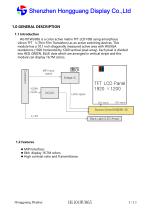
Shenzhen Hongguang Display Co.,Ltd 1.0 GENERAL DESCRIPTION 1.1 Introduction HG101WU065 is a color active matrix TFT LCD FOB using amorphous silicon TFT‘s (Thin Film Transistors) as an active switching devices. This module has a 10.1 inch diagonally measured active area with WUXGA resolutions (1920 horizontal by 1200 vertical pixel array). Each pixel is divided into RED, GREEN, BLUE dots which are arranged in vertical stripe and this module can display 16.7M colors. MIPI input signal LIGHT Panel TFTBACK LCD (Fluorescent Lamp) 1920 ×1200 LVDS signal GOA signal Back Light (LED Array) 1.2 Features...
Open the catalog to page 3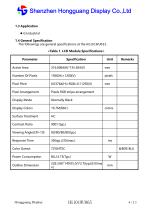
Shenzhen Hongguang Display Co.,Ltd 1.3 Application G Industrial 1.4 General Specification The followings are general specifications at the HG101WU065. Parameter Active Area Pixel Pitch Pixel Arrangement Pixels RGB stripe arrangement Display Mode Normally Black Display Colors Surface Treatment Contrast Ratio Response Time Color Gamut Power Consumption Outline Dimension Hongguang Display
Open the catalog to page 4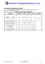
Shenzhen Hongguang Display Co.,Ltd 2.0 ABSOLUTE MAXIMUM RATINGS The followings are maximum values which, if exceed, may cause faulty operation or damage to the unit. < Table 2. Absolute Maximum Ratings> Parameter Operating Temperature Storage Temperature Operating Ambient Humidity Storage Humidity Power Supply Hongguang Display
Open the catalog to page 5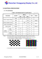
Shenzhen Hongguang Display Co.,Ltd 3.0 ELECTRICAL SPECIFICATIONS 3.1 TFT LCD Module < Table 3. LCD Module Electrical specifications > Parameter Power Supply Voltage Power Supply Current Power Consumption Rush current Input Voltage Output Voltage CMOS Interface Ripple Note 1 Note 2 Notes : 1. The supply voltage is measured and specified at the interface connector of LCM. The current draw and power consumption specified is for VDD=3.3V, Frame rate fV and Clock frequency = 490MHz. Test Pattern of power supply current a) Typ : Mosaic 8 x 6 Pattern(L0/L255) b) Max : skip subPixel(L255) =60Hz 2. The...
Open the catalog to page 6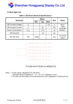
Shenzhen Hongguang Display Co.,Ltd 3.2 Back-Light Unit Table 4. LED Driver Electrical Specifications > Values Notes Note 1 (8pcs Serial 6pcs Parallel.) Power Consumption If=120mA,Vf=25.6V,Lv=400cd/m2 Notes : 1. Power supply voltage25.6V for LED Driver Calculator Value for reference IF × VF ×48/ 85%( efficiency) = PLED 2. The LED Life-time define as the estimated time to 50% degradat
Open the catalog to page 7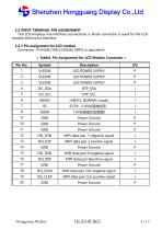
Shenzhen Hongguang Display Co.,Ltd 3.2 INPUT TERMINAL PIN ASSIGNMENT This LCD employs one interface connections, a 34 pin connector is used for the LCD module electronics interface. 3.2.1 Pin assignment for LCD module Connector : FH34SRJ-34S-0.5SH(50) (HRS) or equivalent < Table4. Pin Assignment for LCD Module Connector > Pin No. H,BIST;L NORMAL mode; Power Ground Power Ground Power Ground MIPI data pair 3 negative signal MIPI data pair 3 positive signal Power Ground MIPI data pair 0 negative signal MIPI data pair 0positive signal Power Ground MIPI data pair CLK negative signal MIPI data pair...
Open the catalog to page 8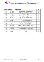
Shenzhen Hongguang Display Co.,Ltd MIPI data pair 1 negative signal MIPI data pair 1positive signal Power Ground MIPI data pair 2negative signal MIPI data pair 2positive signal Power Ground Hongguang Display
Open the catalog to page 9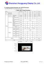
Shenzhen Hongguang Display Co.,Ltd 3.3 Interface timing Parameter and AC/DC Parameter The HG101WU065 is operated by the DE only < Table5. MIPI Timing Parameter > ITEM LCD Frame Rate Pixels Rate Horizontal Active time Horizontal Pulse Width Horizontal Back Porch Horizontal Front Porch Vertical total time Hongguang Display
Open the catalog to page 10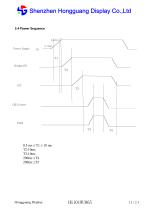
Shenzhen Hongguang Display Co.,Ltd 3.4 Power Sequence Power Supply Hongguang Display
Open the catalog to page 11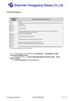
Shenzhen Hongguang Display Co.,Ltd 3.4 Power Sequence
Open the catalog to page 12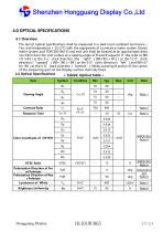
Shenzhen Hongguang Display Co.,Ltd 4.0 OPTICAL SPECIFICATIONS 4.1 Overview The test of optical specifications shall be measured in a dark room (ambient luminance 1lux and temperature = 252℃) with the equipment of Luminance meter system (Gonio meter system and TOPCON BM-5) and test unit shall be located at an approximate dista nce 50cm from the LCD surface at a viewing angle of θ and Φ equal to 0. We refer to θØ =0 (=θ3 ) as the 3 o’clock direction (the “right”), θØ=90 (= θ12 ) as the 12 O’clock direction (“upward”), θØ=180 (= θ9 ) as the 9 O’clock direction (“left”) and θØ=27 0(= θ6 ) as...
Open the catalog to page 13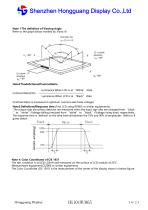
Shenzhen Hongguang Display Co.,Ltd Note 1:The definition of Viewing Angle Refer to the graph below marked by θ and Ф. Luminance When LCD is at “White” state Luminance When LCD is at “Black” state (Contrast Ratio is measured in optimum common electrode voltage) Note3:DefinitionofResponse time.(Test LCD using RD80S or similar equipments): The output sign also photo detector are measured when the input sign also are changed from “black ” to “white”(Voltage falling time)and from “white” to “black” (Voltage rising time), respectively . The response time is defined as the time interval between the...
Open the catalog to page 14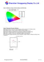
Shenzhen Hongguang Display Co.,Ltd Note 5: Definition of Color of CIE Coordinate and NTSC Ratio. Note 6: Polarization Direction Definition Viewing direction is normal user viewing direction which is vertical to the display surface The polarizer which is closer to viewer is defined as Front Polarizer The polarizer which is on the rear side of viewer is defined as Rear Polarizer The X axis is defined as parallel line to top & bottom sidelines of the Active Area PdF which is marked in blue arrow is polarization degree of Front polarizer PdB which is marked in red arrow is polarization degree...
Open the catalog to page 15All Shenzhen Hongguang Display Co., Ltd catalogs and technical brochures
 HG215FH008T01
30 Pages
 HG185FH005
21 Pages
 HG170SX006T01
20 Pages
 HG160WQ004
64 Pages
 HG156FH011
23 Pages
 HG133FH017T01
32 Pages
 HG121WX001T01
22 Pages
 HG116FH008
24 Pages
 HG104SV003
27 Pages
 HG101WX054
12 Pages
 HG101WX053
12 Pages
 HG101WX049
38 Pages
 HG101WX047T01
19 Pages
 HG101WX047
19 Pages
 HG101WX046
18 Pages
 HG101WX030
24 Pages
 HG101WX028
21 Pages
 HG101WX026T01
20 Pages
 HG101WX025
19 Pages
 HG101WX022
19 Pages
 HG101WX021T01
20 Pages
 HG101WX021
20 Pages
 HG050WV038
18 Pages
 HG101WX019T01
20 Pages
 HG101WX019
20 Pages
 HG101WX016
20 Pages
 HG101WX005T01
22 Pages
 HG101WU076
25 Pages
 HG101WU072T01
23 Pages
 HG101WU072
23 Pages
 HG101WU063
24 Pages
 HG101WU062
27 Pages
 HG101WU039
30 Pages
 HG101WU035
23 Pages
 HG101WU032T01
18 Pages
 HG101WU013
17 Pages
 HG101WU010
17 Pages
 HG101WU008T01
17 Pages
 HG101WS045
22 Pages
 HG101WS042
17 Pages
 HG101WS040
19 Pages
 HG101WQ004T01
13 Pages
 HG101WQ003
13 Pages
 HG097XG006T01
17 Pages
 HG097QX005
17 Pages
 HG097QX003Z05
18 Pages
 HG097QX003T02
18 Pages
 HG097QX003T01
18 Pages
 HG090WS008
19 Pages
 HG080WX034
19 Pages
 HG080WX032
12 Pages
 HG080WX015
19 Pages
 HG080WX013
19 Pages
 HG080WV029
20 Pages
 HG080WV027
22 Pages
 HG080WU018T01
19 Pages
 HG080WU009
14 Pages
 HG070WX006
13 Pages
 HG070WX005
19 Pages
 HG070WS051T01
19 Pages
 HG070WV048
23 Pages
 HG070WV047
23 Pages
 HG070WV037R01
20 Pages
 HG070WV035T01
19 Pages
 HG070WV035
18 Pages
 HG070WV031
12 Pages
 HG070WV026
23 Pages
 HG070WV022
23 Pages
 HG070WV020
12 Pages
 HG070WV013T01
20 Pages
 HG070WV013R02
20 Pages
 HG070WU039
25 Pages
 HG070WS055
14 Pages
 HG070WS052
13 Pages
 HG070WV051T01
19 Pages
 HG070WS050
22 Pages
 HG070WS049T02
13 Pages
 HG070WS049T01
13 Pages
 HG070WS049-V1
21 Pages
 HG070WS048
25 Pages
 HG070WS046T03
13 Pages
 HG050HD030-V3
18 Pages
 HG215FH008T02
30 Pages
 HG104SV004
21 Pages
 HG050HD030T01
18 Pages
Archived catalogs
 HG043HV026
16 Pages
 HG024QV023R01
1 Page
 HG030FH006T02
16 Pages
 HG055FH018T01
20 Pages
 HG055HD017
16 Pages
 HG055FH021
20 Pages
 HG005WS003
39 Pages
 HG007WS003
50 Pages
 HG010WZ003
50 Pages
 HG015WZ003
49 Pages
 HG080STD02C
7 Pages
 HG104VG002-V0
20 Pages
 HG215FH008
30 Pages
 HG097XG008
17 Pages
 HGYD2690H-V1
21 Pages
 HG173FH002G01
30 Pages
 HG173FH002
30 Pages
 HG043HV002T02
17 Pages
 HG050WV009
19 Pages
 HG028HS003
15 Pages
 HG032WV001
17 Pages
 HG032XG003
19 Pages
 HG034SV004
14 Pages
 HG035SV003
22 Pages
 HG039WV004
19 Pages
 HG040HH005
16 Pages
 HG040HS002T01
16 Pages
 HG040WV006T02
18 Pages
 HG043HV002P01
10 Pages
 HG043HV002R03
17 Pages
 HG043WV005T01
19 Pages
 HG140FH005
20 Pages
 HG043HV008
17 Pages
 HG043HV008T01
17 Pages
 HG043HV009
21 Pages
 HG043HV010
21 Pages
 HG050WV010
19 Pages
 HG030FW006
14 Pages
 HG043HV022
16 Pages
 HG043HV028
20 Pages
 HG043WV016
18 Pages
 HG043WV023T01
19 Pages
 HG043HV029
19 Pages
 HG080WX039-V0
19 Pages
 HG050FH028T02
18 Pages
 HG050HD026T01
18 Pages
 HG101WU042-V0
29 Pages
 HG060HD012
18 Pages
 HG025HV006
12 Pages
 HG050QZ002
21 Pages
 HG050WV005
18 Pages
 HG050WV005T01
18 Pages
 HG050WV008T01
20 Pages
 HG050WV09G01
19 Pages
 HG050WV032
10 Pages
 HG050WV032T01
10 Pages
 HG050WV033
10 Pages
 HG050WV034
20 Pages
 HG055HD016T01
19 Pages
 HG062WV003
19 Pages
 HG062WV006
20 Pages
 HG064XG003
20 Pages
 HG069HS004
20 Pages
 HG070WS004T06
13 Pages
 HG070WS011
13 Pages
 HG070WS012
26 Pages
 HG070WS002
13 Pages
 HG070WS004P01
22 Pages
 HG070WS013
24 Pages
 HG070WS018
19 Pages
 HG070WS045
13 Pages
 HG070WS045T01
13 Pages
 HG070WS045T02
13 Pages
 HG070WS046T02
13 Pages

- LCD display panel
- Industrial display panel
- TFT display module
- Touch screen display panel
- Color display panel
- LED display panel
- Electronic display panel
- Control display system
- IPS display panel
- Programmable display system
- Information display
- RS-232 display panel
- Outdoor display panel
- Built-in display
- Instrumentation display panel
- Medical equipment display
- Graphic display panel
- RGB display panel
- Control panel display panel