- Company
- Products
- Catalogs
- News & Trends
- Exhibitions
HG070WV048
1 /23Pages
HG070WV048
1 /23Pages
Catalog excerpts

Shenzhen Hongguang Display Co.,Ltd CUSTOMER : CUSTOMER MODULE : HL MODEL ■Final Specification Customer Confirmation column: Dept. : Please return one of the copies of the specification with your signature to us within two weeks after you receive this document.If it is not returned,we will assume that you agree to the entire contents of this specification document. Hongguang Display
Open the catalog to page 1
Shenzhen Hongguang Display Co.,Ltd Revision History Version NO. Hongguang Display FIRST ISSUE
Open the catalog to page 2
Hongguang Display
Open the catalog to page 3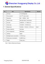
Shenzhen Hongguang Display Co.,Ltd 1. General Specifications No. Driver element Display mode Normally White, Transmissive Active area Module size Surface treatment Color arrangement Backlight power consumption Panel power consumption Note 1: Refer to Mechanical Drawing. Hongguang Display
Open the catalog to page 4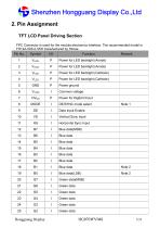
Shenzhen Hongguang Display Co.,Ltd 2. Pin Assignment TFT LCD Panel Driving Section FPC Connector is used for the module electronics interface. The recommended model is FH12A-50S-0.5SH manufactured by Hirose. Pin No. Power for LED backlight (Anode) Power for LED backlight (Anode) Power for LED backlight (Cathode) Power for LED backlight (Cathode) Power ground Common voltage Power for Digital Circuit DE/SYNC mode select Data Input Enable Vertical Sync Input Horizontal Sync Input Blue data(MSB) Blue data Blue data Blue data Blue data Blue data Blue data Blue data(LSB) Green data(MSB) Green data...
Open the catalog to page 5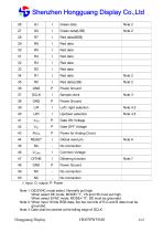
Shenzhen Hongguang Display Co.,Ltd 26 Green data Green data(LSB) Power Ground Sample clock Power Ground Left / right selection Up/down selection Power for Analog Circuit Common Voltage Dithering function Power Ground I: input, O: output, P: Power Note 1: DE/SYNC mode select. Normally pull high. When select DE mode, MODE=”1”, VS and HS must pull high. When select SYNC mode, MODE= ”0”, DE must be grounded. Note 2: When input 18 bits RGB data, the two low bits of R,G and B data must be grounded. Note 3: Data shall be latched at the falling edge of DCLK. Hongguang Display
Open the catalog to page 6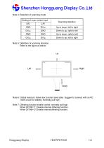
Shenzhen Hongguang Display Co.,Ltd Note 4: Selection of scanning mode Setting of scan control input Scanning direction Up to down, left to right Down to up, right to left Up to down, right to left Down to up, left to right Note 5: Definition of scanning direction. Refer to the figure as below: Note 6: Global reset pin. Active low to enter reset state. Suggest to connect with an RC reset circuit for stability. Normally pull high. Note 7: Dithering function enable control, normally pull high. When DITHB=”1”,Disable internal dithering function, When DITHB=”0”,Enable internal dithering function,...
Open the catalog to page 7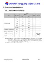
Shenzhen Hongguang Display Co.,Ltd 3. Operation Specifications 3.1. Absolute Maximum Ratings (Note 1) Values Item Operation Temperature Storage Temperature Power voltage Note 1: The absolute maximum rating values of this product are not allowed to be exceeded at any times. Should a module be used with any of the absolute maximum ratings exceeded, the characteristics of the module may not be recovered, or in an extreme case, the module may be permanently destroyed. Note 2: VR Conditions: Zener Diode 20mA Hongguang Display
Open the catalog to page 8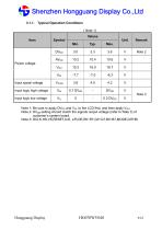
Shenzhen Hongguang Display Co.,Ltd 3.1.1. Typical Operation Conditions ( Note 1) Values Input logic high voltage Input logic low voltage Power voltage Input signal voltage Note 1: Be sure to apply DVDD and VGL to the LCD first, and then apply VGH. Note 2: DVDD setting should match the signals output voltage (refer to Note 3) of customer’s system board. Note 3: DCLK,HS,VS,RESET,U/D, L/R,DE,R0~R7,G0~G7,B0~B7,MODE,DITHB. Hongguang Display
Open the catalog to page 9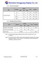
Shenzhen Hongguang Display Co.,Ltd 3.1.2. Current Consumption Values Symbol IDVDD IAVDD Backlight Driving Conditions Values Note 1: The LED Supply Voltage is defined by the number of LED at Ta=25℃ and IL =180mA. Note 2: The “LED life time” is defined as the module brightness decrease to 50% original brightness at Ta=25℃ and IL =180mA. The LED lifetime could be decreased if operating IL is lager than 180mA. Hongguang Display
Open the catalog to page 10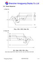
Shenzhen Hongguang Display Co.,Ltd 3.2. Power Sequence a. Power on: DVDD→VGL→ →VGH→ →Data→ → →B/L b. Power off: B/L→ →Data→ →VGH→ →VGL→ → →DVDD Note: Data include R0~R7, B0~B7, GO~G7, U/D, L/R, DCLK, HS,VS,DE.
Open the catalog to page 11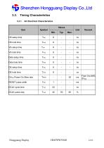
Shenzhen Hongguang Display Co.,Ltd 3.3. AC Electrical Characteristics Values Data setup time Data hole time DVDD Power On Slew rate RESET pulse width DCLK cycle time DCLK pulse duty Hongguang Display
Open the catalog to page 12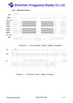
Shenzhen Hongguang Display Co.,Ltd 3.3.2. Data Input Format Hongguang Display
Open the catalog to page 13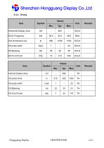
Shenzhen Hongguang Display Co.,Ltd 3.3.3. Timing Values Item Horizontal Display Area DCLK Frequency One Horizontal Line HS pulse width Values Item Vertical Display Area Hongguang Display
Open the catalog to page 14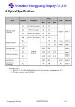
Shenzhen Hongguang Display Co.,Ltd 4. Optical Specifications Values Item Note 2 Note 5 Note 6 Luminance uniformity Response time Contrast ratio Test Conditions: 1. DVDD=3.3V, IL=180mA (Backlight current), the ambient temperature is 25℃. 2. The test systems refer to Note 2.
Open the catalog to page 15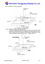
Shenzhen Hongguang Display Co.,Ltd Note 1: Definition of viewing angle range Normal line θ=Φ=0° Φ=270° 6 o’clock direction Fig. 4-1 Definition of viewing angle Note 2: Definition of optical measurement system. The optical characteristics should be measured in dark room. After 30 minutes operation, the optical properties are measured at the center point of the LCD screen. (Response time is measured by Photo detector TOPCON BM-7, other items are measured by BM-5A/Field of view: 1° /Height: 500mm.) Photo detector Normal line θ=Φ=0° Φ=90° 12 o’clock direction Φ=0° Active Area LCM Φ=270° 6 o’clock...
Open the catalog to page 16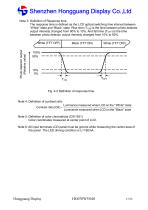
Shenzhen Hongguang Display Co.,Ltd Note 3: Definition of Response time The response time is defined as the LCD optical switching time interval between “White” state and “Black” state. Rise time (TON) is the time between photo detector output intensity changed from 90% to 10%. And fall time (TOFF) is the time between photo detector output intensity changed from 10% to 90%. Photo detector output (Relative value) Fig. 4-3 Definition of response time Note 4: Definition of contrast ratio Contrast ratio (CR) = Luminance measured when LCD on the " White" state Luminance measured when LCD on the " Black"...
Open the catalog to page 17All Shenzhen Hongguang Display Co., Ltd catalogs and technical brochures
 HG215FH008T01
30 Pages
 HG185FH005
21 Pages
 HG170SX006T01
20 Pages
 HG160WQ004
64 Pages
 HG156FH011
23 Pages
 HG133FH017T01
32 Pages
 HG121WX001T01
22 Pages
 HG116FH008
24 Pages
 HG104SV003
27 Pages
 HG101WX054
12 Pages
 HG101WX053
12 Pages
 HG101WX049
38 Pages
 HG101WX047T01
19 Pages
 HG101WX047
19 Pages
 HG101WX046
18 Pages
 HG101WX030
24 Pages
 HG101WX028
21 Pages
 HG101WX026T01
20 Pages
 HG101WX025
19 Pages
 HG101WX022
19 Pages
 HG101WX021T01
20 Pages
 HG101WX021
20 Pages
 HG050WV038
18 Pages
 HG101WX019T01
20 Pages
 HG101WX019
20 Pages
 HG101WX016
20 Pages
 HG101WX005T01
22 Pages
 HG101WU076
25 Pages
 HG101WU072T01
23 Pages
 HG101WU072
23 Pages
 HG101WU065
23 Pages
 HG101WU063
24 Pages
 HG101WU062
27 Pages
 HG101WU039
30 Pages
 HG101WU035
23 Pages
 HG101WU032T01
18 Pages
 HG101WU013
17 Pages
 HG101WU010
17 Pages
 HG101WU008T01
17 Pages
 HG101WS045
22 Pages
 HG101WS042
17 Pages
 HG101WS040
19 Pages
 HG101WQ004T01
13 Pages
 HG101WQ003
13 Pages
 HG097XG006T01
17 Pages
 HG097QX005
17 Pages
 HG097QX003Z05
18 Pages
 HG097QX003T02
18 Pages
 HG097QX003T01
18 Pages
 HG090WS008
19 Pages
 HG080WX034
19 Pages
 HG080WX032
12 Pages
 HG080WX015
19 Pages
 HG080WX013
19 Pages
 HG080WV029
20 Pages
 HG080WV027
22 Pages
 HG080WU018T01
19 Pages
 HG080WU009
14 Pages
 HG070WX006
13 Pages
 HG070WX005
19 Pages
 HG070WS051T01
19 Pages
 HG070WV047
23 Pages
 HG070WV037R01
20 Pages
 HG070WV035T01
19 Pages
 HG070WV035
18 Pages
 HG070WV031
12 Pages
 HG070WV026
23 Pages
 HG070WV022
23 Pages
 HG070WV020
12 Pages
 HG070WV013T01
20 Pages
 HG070WV013R02
20 Pages
 HG070WU039
25 Pages
 HG070WS055
14 Pages
 HG070WS052
13 Pages
 HG070WV051T01
19 Pages
 HG070WS050
22 Pages
 HG070WS049T02
13 Pages
 HG070WS049T01
13 Pages
 HG070WS049-V1
21 Pages
 HG070WS048
25 Pages
 HG070WS046T03
13 Pages
 HG050HD030-V3
18 Pages
 HG215FH008T02
30 Pages
 HG104SV004
21 Pages
 HG050HD030T01
18 Pages
Archived catalogs
 HG043HV026
16 Pages
 HG024QV023R01
1 Page
 HG030FH006T02
16 Pages
 HG055FH018T01
20 Pages
 HG055HD017
16 Pages
 HG055FH021
20 Pages
 HG005WS003
39 Pages
 HG007WS003
50 Pages
 HG010WZ003
50 Pages
 HG015WZ003
49 Pages
 HG080STD02C
7 Pages
 HG104VG002-V0
20 Pages
 HG215FH008
30 Pages
 HG097XG008
17 Pages
 HGYD2690H-V1
21 Pages
 HG173FH002G01
30 Pages
 HG173FH002
30 Pages
 HG043HV002T02
17 Pages
 HG050WV009
19 Pages
 HG028HS003
15 Pages
 HG032WV001
17 Pages
 HG032XG003
19 Pages
 HG034SV004
14 Pages
 HG035SV003
22 Pages
 HG039WV004
19 Pages
 HG040HH005
16 Pages
 HG040HS002T01
16 Pages
 HG040WV006T02
18 Pages
 HG043HV002P01
10 Pages
 HG043HV002R03
17 Pages
 HG043WV005T01
19 Pages
 HG140FH005
20 Pages
 HG043HV008
17 Pages
 HG043HV008T01
17 Pages
 HG043HV009
21 Pages
 HG043HV010
21 Pages
 HG050WV010
19 Pages
 HG030FW006
14 Pages
 HG043HV022
16 Pages
 HG043HV028
20 Pages
 HG043WV016
18 Pages
 HG043WV023T01
19 Pages
 HG043HV029
19 Pages
 HG080WX039-V0
19 Pages
 HG050FH028T02
18 Pages
 HG050HD026T01
18 Pages
 HG101WU042-V0
29 Pages
 HG060HD012
18 Pages
 HG025HV006
12 Pages
 HG050QZ002
21 Pages
 HG050WV005
18 Pages
 HG050WV005T01
18 Pages
 HG050WV008T01
20 Pages
 HG050WV09G01
19 Pages
 HG050WV032
10 Pages
 HG050WV032T01
10 Pages
 HG050WV033
10 Pages
 HG050WV034
20 Pages
 HG055HD016T01
19 Pages
 HG062WV003
19 Pages
 HG062WV006
20 Pages
 HG064XG003
20 Pages
 HG069HS004
20 Pages
 HG070WS004T06
13 Pages
 HG070WS011
13 Pages
 HG070WS012
26 Pages
 HG070WS002
13 Pages
 HG070WS004P01
22 Pages
 HG070WS013
24 Pages
 HG070WS018
19 Pages
 HG070WS045
13 Pages
 HG070WS045T01
13 Pages
 HG070WS045T02
13 Pages
 HG070WS046T02
13 Pages

- LCD display panel
- Industrial display panel
- TFT display module
- Touch screen display panel
- Color display panel
- LED display panel
- Electronic display panel
- Control display system
- IPS display panel
- Programmable display system
- Information display
- RS-232 display panel
- Outdoor display panel
- Built-in display
- Instrumentation display panel
- Medical equipment display
- Graphic display panel
- RGB display panel
- Control panel display panel