- Catalogs
- Shenyang Vhandy Technology Co.
- GCAN-PLC-400
- Company
- Products
- Catalogs
- News & Trends
- Exhibitions
GCAN-PLC-400
1 /31Pages

GCAN-PLC-400
1 /31Pages
Catalog excerpts

Vhandy technology GCAN-PLC user manual GCAN-PLC-400 Programmable Logic Controller User manual
Open the catalog to page 1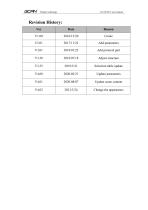
Vhandy technology GCAN-PLC user manual Adjust structure Selection table update Update parameters Update some content
Open the catalog to page 2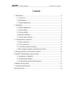
Vhandy technology GCAN-PLC user manual
Open the catalog to page 3
Vhandy technology GCAN-PLC user manual 1. Introduction 1.1. Overview GCAN-PLC-400 programmable logic controller is a bus module controller integrated with PLC function. It has the characteristics of compact, costeffective, can be used to connect the CAN-Bus system, Modbus system and distributed bus terminal module, and these terminal modules can be expanded in a modular way. A complete control system consists of a bus module controller (GCANPLC-400),1-32 arbitrary number of GC series terminal modules (GC-1008, GC-3804, etc.) and a terminal module. The GCAN-PLC-400 supports automatic configuration....
Open the catalog to page 4
Vhandy technology GCAN-PLC user manual One-channel CAN-Bus interface, one-channel Ethernet interface, one-channel RS232/485 (multiplexed) serial interface Programming Software: OpenPCS ( according to IEC 61131-3standard) Support CANopen protocol master/slave function Support Modbus RTU/TCP master/slave function In the case of sufficient power supply (plus expansion power modules), the number of expandable IO modules is up to 32 (up to 32x8 DI/DO points) Transmit 4 PDOs ( CANopen) and receive 4 PDOs (CANopen) Configuration mode is automatic configuration Supply power: DC+24V Input current, 400mA+...
Open the catalog to page 5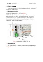
Vhandy technology GCAN-PLC user manual 2. Installation This chapter introduces the method installation and wiring, the meaning of the indicator and the interface. 2.1 Module appearance GCAN-PLC-400 appearance as shown in Figure 2.1 GCAN-PLC-400 includes three communication interfaces, a controller programming interface, a set of controller power interface, two sets of I/O power interfaces, two sets of Shielding line interfaces. Among them, the communication interface includes one Ethernet interface, one CAN-Bus interface and one RS232/RS485interface. 2.2 Fixed module GCAN-PLC-400 and its matching...
Open the catalog to page 6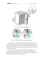
Vhandy technology GCAN-PLC user manual Figure 2.3 GCAN-PLC-400 self-locking mechanism As shown figure 2.2, install the GCAN-PLC-400 on the guide rail until the lock is stuck. Then you need to rotate the orange knob on the left end of the controller counterclockwise to fix the left end of the controller on the guide rail. The GCAN-PLC-400 has a self-locking mechanism that can effectively prevent equipment from falling. As shown figure 2.3, you can release the self-locking mechanism by pulling out the orange label and take out the controller or matching terminal module. Before taking out the controller,...
Open the catalog to page 7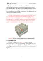
Vhandy technology GCAN-PLC user manual The GCAN-PLC-400 can connect up to 32 distributed bus terminal modules. When inserting the GC series terminal module, be sure to insert it along the groove on the right side of the existing module sequentially until the lock is stuck. When you assemble the nodes correctly, there is no obvious gap between the terminal modules. If the modules are not assembled correctly, the entire node will not operate normally. Please note: When using the GCAN-PLC-400, you must ensure that you have installed terminal modul at the right end of the entire node, and the terminal...
Open the catalog to page 8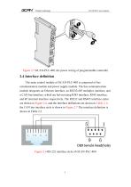
Vhandy technology GCAN-PLC user manual Figure 2.5 GCAN-PLC-400, the power wiring of programmable controller 2.4 Interface definition The main control module of GCAN-PLC-400 is composed of bus communication module and power supply module. The bus communication module integrates an Ethernet interface, an RS232/485 multiplex interface, and a CAN bus interface, which are led out using RJ45 interface, RJ45 interface, and 4P terminal interface respectively. The RS232 and RS485 interface styles are shown in Figure 2.6, and the interface definitions are shown in Table 2.1; the CAN bus interface style...
Open the catalog to page 9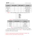
Vhandy technology GCAN-PLC user manual RS232 data send RS232 data receive Signal ground RS485 signalA+ RS48 signal B- Table 2.1 RS232 and RS485 interface definition of GCAN-PLC-400 Figure 2.7 CAN bus terminal block of GCAN-PLC-400 Terminal Serial number CAN-H 1 CAN bus-high SHIELD 2 Shield CAN-L 3 CAN bus-low CAN-G 4 CAN bus-GND Table 2.2 CAN bus terminal definition of GCAN-PLC-400 The power wiring terminal block of GCAN-PLC-400 is shown in Figure 2.8, and its interface definition is shown in Table 2.3. The power supply part of GCAN-PLC-400 contains 8 terminals. Note that: connecting between...
Open the catalog to page 10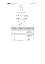
Vhandy technology GCAN-PLC user manual Figure 2.8 GCAN-PLC-400, Power terminal block Terminal Input 24V power GND power IO positive power IO positive power IO negative power IO negative power shield shield Table 2.3 GCAN-PLC-400, terminal definition
Open the catalog to page 11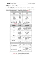
Vhandy technology GCAN-PLC user manual 2.5 System status indicator GCAN-PLC-400 has two sets of status indicators, contains 6 circular status indicators in the left area and 2 power indicators in the right area. The specific indicating function of the indicator is shown in table 2.4. Indicator green green green green green green green green Power System Run Error GC-Bus run GC-Bus error Power GC-Bus power Table 2.4 GCAN-PLC-400, indicators Indicator PWR SYS RUN ERR IO RUN IO ERR bright not bright Blinking not bright Blinking not bright bright not bright Blinking not bright bright not bright Power...
Open the catalog to page 12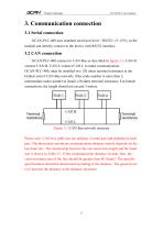
Vhandy technology GCAN-PLC user manual 3. Communication connection 3.1 Serial connection GCAN-PLC-400 uses standard serial port level(RS232: ±3~15V), so the module can directly connect to the device with RS232 interface. 3.2 CAN connection GCAN-PLC-400 connect to CAN-Bus as described in figure 3.1, CAN-H connect CAN-H, CAN-L connect CAN L to make communication. GCAN-PLC-400, must be installed two 120 ohms terminal resistance at the farthest end of CAN-Bus network; if the node number is more than 2, intermediate nodes needn't to install 120 ohms terminal resistance. For branch connections, the...
Open the catalog to page 13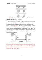
Vhandy technology GCAN-PLC user manual Baud rate 1 Mbit/s 500 kbit/s 250 kbit/s 125 kbit/s 50 kbit/s 20 kbit/s 10 kbit/s 5 kbit/s Table 3.1 the relationship between CAN-Bus length and baud rate. 3.3. CAN-Bus terminal resistance In order to enhance the reliability of CAN communication and eliminate the interference of CAN bus terminal signal reflection, the two farthest endpoints of the CAN bus network usually need to add terminal matching resistors, as shown in Figure 3.2. The value of the terminal matching resistance is determined by the characteristic impedance of the transmission cable. For...
Open the catalog to page 14All Shenyang Vhandy Technology Co. catalogs and technical brochures
 GC-8012 Power Supply Module
12 Pages
 GC-2302-2 Channel PWM Module
15 Pages
 GC-2204-4 Channel Relay Output
13 Pages
 GC-2018-8DO(NPN)
13 Pages
 GC-2008-8DO(PNP)
13 Pages
 GC-1502-2Channel Counter Module
13 Pages
 GC-1018-8DI(NPN)
13 Pages
 GC-1008-8DI(PNP)
13 Pages
 GCAN-IO-8100
20 Pages
 GCAN-IO-8000
25 Pages
 GCAN-PLC-511
31 Pages
 GCAN-PLC-510
31 Pages


