- Catalogs
- Shenyang Vhandy Technology Co.
- GCAN-IO-8000
- Company
- Products
- Catalogs
- News & Trends
- Exhibitions
GCAN-IO-8000
1 /25Pages

GCAN-IO-8000
1 /25Pages
Catalog excerpts

GCAN-IO-8000 CANopen I/O coupler User manual
Open the catalog to page 1
Vhandy technology Revision History: Create Fixed working parameters Add parameters Add protocol section Fixed parameters Modify the selection table Product revision and upgrade
Open the catalog to page 2
Vhandy technology
Open the catalog to page 3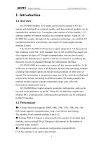
Vhandy technology 1. Introduction 1.1 Overview GCAN-8000 Modbus I/O Coupler can be used to connect CAN bus system and distributed bus terminal module, and these terminal modules can be expanded in a modular way. A complete node consists of a bus coupler, 1-32 arbitrary number of terminal modules and a terminal module. Adopt GCANIO-8000 bus coupler, through GC-bus expansion technology, can establish I/O connection extremely conveniently, can connect 32 input/output terminal modules at most. The GCAN-IO-8000 CANopen bus coupler adopts the CAN bus protocol that conforms to the ISO 11898 standard....
Open the catalog to page 4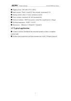
Vhandy technology ● Supply power: 24V DC(-15%/+20%) ● Input current, 70mA+ (total GC-bus current), maximum2.5A ● Starting current: about 2.5 times continuous current ● Power contacts: maximum 24V DC/maximum10A ● Electrical isolation: 1500 Vrms (power contact/bus coupled power voltage) ● Working temperature: -40.00℃~85.00℃ ● Dimensions:100mm(L) * 69mm(W) * 48mm(H) 1.3 Typical application ● Connect with the distributed bus terminal module to form a complete control node. ● Perform data acquisition and data transmission with
Open the catalog to page 5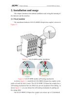
Vhandy technology 2. Installation and usage This chapter introduces the method installation and wiring,the meaning of the indicator and the interface. 2.1 Fixed module The installation method of GCAN-8000CANopen bus coupler is shown in Figure 2.1 Figure 2.1 GCAN-8000 module installation Figure 2.2 GCAN-8000 module self-locking mechanism As shown figure 2.1, install the GCAN-8000CANopen bus coupler on the guide rail until the lock is stuck. The GCAN-8000 CANopen bus coupler has a self-locking mechanism that can effectively prevent equipment from falling. As shown figure 2.2, you can release the...
Open the catalog to page 6
Vhandy technology bus terminal modules. When inserting bus terminal module, be sure to insert it along the groove on the right side of the existing module sequentially until the lock is stuck. At the right end of the entire node, you need to install terminal module. The terminal will guarantee the data transmission and power supply of the GC-Bus. When you assemble the nodes correctly, there is no obvious gap between the terminal modules. If the modules are not assembled correctly, the entire node will not operate normally. 2.2 Wiring method The power wiring as shown in figure 2.3. First, use...
Open the catalog to page 7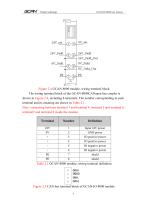
Vhandy technology Figure 2.4 GCAN-8000 module, wiring terminal block The wiring terminal block of the GCAN-8000CANopen bus coupler is shown in Figure 2.4, including 8 terminals. The number corresponding to each terminal and its meaning are shown in Table 2.1. Note: connecting between terminal 3 and terminal 4, terminal 5 and terminal 6, terminal7 and terminal 8 inside the module. Terminal Input 24V power GND power IO positive power IO positive power IO negative power IO negative power shield shield Table 2.1 GCAN-8000 module, wiring terminal definition Figure 2.5 CAN bus terminal block of GCAN-IO-8000...
Open the catalog to page 8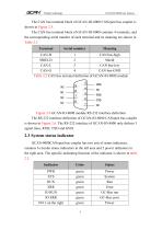
Vhandy technology The CAN bus terminal block of GCAN-IO-8000 CANopen bus coupler is shown in Figure 2.5. The CAN bus terminal block of GCAN-IO-8000 contains 4 terminals, and the corresponding serial number of each terminal and its meaning are shown in Table 2.2 Terminal Serial number CAN-H 1 CAN bus-high SHIELD 2 Shield CAN-L 3 CAN bus-low CAN-G 4 CAN bus-GND Table 2.2 CAN bus terminal definition of GCAN-IO-8000 module Figure 2.6 GCAN-IO-8000 module RS-232 interface definition The RS-232 interface definition of GCAN-IO-8000 CANopen bus coupler is shown in Figure 2.6. The RS-232 interface of GCAN-IO-8000...
Open the catalog to page 9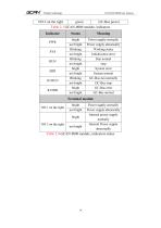
Vhandy technology NO.3 on the right green GC-Bus power Table 2.3 GCAN-8000 module, indicators Indicator PWR SYS RUN ERR IO RUN IO ERR bright not bright Blinking not bright Blinking not bright bright not bright Blinking not bright bright not bright Power supply normally Power supply abnormally Working status Initialization error Run normal stop System error System normal GC-Bus run normally GC-Bus stop GC-Bus error GC-Bus normal Terminal module NO.1 on the right bright not bright bright Power supply normally Power supply abnormally Internal power supply normally Internal Power supply abnormally...
Open the catalog to page 10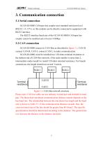
Vhandy technology 3. Communication connection 3.1 Serial connection GCAN-IO-8000 CANopen bus coupler uses standard serial port level (RS232: ±3~15V), so this module can be directly connected to equipment with RS232 interface. The RS232 interface baud rate of the GCAN-IO-8000 CANopen bus coupler cannot be modified and is fixed at 19200bps. 3.2 CAN connection GCAN-IO-8000 connect to CAN-Bus as described in figure 3.1, CAN-H connect CAN-H, CAN-L connect CAN L to make communication. GCAN-IO-8000, must be installed two 120 ohms terminal resistance at the farthest end of CAN-Bus network; if the node...
Open the catalog to page 11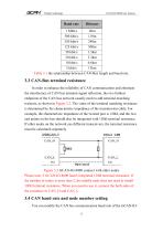
Vhandy technology Baud rate 1 Mbit/s 40m 500 kbit/s 110m 250 kbit/s 240m 125 kbit/s 500m 50 kbit/s 1.3km 20 kbit/s 3.3km 10 kbit/s 6.6km 5 kbit/s 13km Table 3.1 the relationship between CAN-Bus length and baud rate. 3.3 CAN-Bus terminal resistance In order to enhance the reliability of CAN communication and eliminate the interference of CAN bus terminal signal reflection, the two farthest endpoints of the CAN bus network usually need to add terminal matching resistors, as shown in Figure 3.2. The value of the terminal matching resistance is determined by the characteristic impedance of the transmission...
Open the catalog to page 12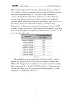
Vhandy technology 8000 module through the RS232 interface. The specific process is as follows: First, establish a serial port connection with a baud rate of 19200bps, configure the data bit and stop bit as none, 8, 1, and send a "help" command or "?" command through the RS232 interface, and then the RS232 interface will return to the configuration information. Please note that when sending the command, please add a carriage return at the end or select "Send New Line" in the software. Do not select "Hexadecimal Display" or "Hexadecimal Transmission" for display and transmission. You can send "setbaud=500000"...
Open the catalog to page 13All Shenyang Vhandy Technology Co. catalogs and technical brochures
 GC-8012 Power Supply Module
12 Pages
 GC-2302-2 Channel PWM Module
15 Pages
 GC-2204-4 Channel Relay Output
13 Pages
 GC-2018-8DO(NPN)
13 Pages
 GC-2008-8DO(PNP)
13 Pages
 GC-1502-2Channel Counter Module
13 Pages
 GC-1018-8DI(NPN)
13 Pages
 GC-1008-8DI(PNP)
13 Pages
 GCAN-IO-8100
20 Pages
 GCAN-PLC-511
31 Pages
 GCAN-PLC-510
31 Pages
 GCAN-PLC-400
31 Pages


- Digital I/O
- IO module
- Analog I/O
- Digital IO module
- Communication gateway
- Industrial gateway
- Ethernet gateway
- Fieldbus gateway
- Programmable logic controller
- Fieldbus I/O module
- Serial gateway
- Analog IO module
- Serial I/O
- DIN rail converter
- Ethernet converter
- DIN rail mounted I O module
- RS-485 gateway
- Communication module
- Compact I/O
- RS-232 gateway