- Catalogs
- Shenyang Vhandy Technology Co.
- GC-2302-2 Channel PWM Module
- Company
- Products
- Catalogs
- News & Trends
- Exhibitions
GC-2302-2 Channel PWM Module
1 /15Pages

GC-2302-2 Channel PWM Module
1 /15Pages
Catalog excerpts

GC-2302 2-channel pulse output module User manual
Open the catalog to page 1
Revision History Modify device parameters Amend the new version parameters Modify product appearance
Open the catalog to page 2
1. Introduction 1.1 Overview The GC-2302 module has integrated 2 pulse output channels, which can send PWM signals and receive control signal from the GCAN-PLC-400/510 or GCAN-IO-8000 coupler. This module can be used with any other GC Series IO module to capture and process digital data in industrial automation or distributed control systems. 1.2 Properties at a glance ● 2 pulse output channels ● Output pulse: 5V ● Maximum output frequency: 100kHz ● Electrical isolation: 500 V(GC-bus) ● Eachpulseoutputthreesignals,includingpulsesignal,directionsignal,enable signal 32bit pulse output register...
Open the catalog to page 4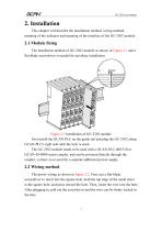
2. Installation This chapter will describe the installation method, wiring method, meaning of the indicator and meaning of the interface of the GC-2302 module. 2.1 Module fixing The installation method of GC-2302 module as shown in Figure 2.1 and a flat-blade screwdriver is needed for auxiliary installation. Figure 2.1 Installation of GC-2302 module First install the GCAN-PLC on the guide rail and plug the GC-2302 along GCAN-PLC's right side until the lock is stuck. The GC-2302 module needs to be used with a GCAN-PLC-400/510 or GCAN-IO-8000 series coupler, and can be powered directly through...
Open the catalog to page 5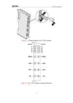
Figure 2.2 Wiring method of GC-2302 module Figure 2.3 GC-2302 module terminal definition
Open the catalog to page 6
GC-2302 contains 2 sets of pulse output, and the meaning of indicators are shown in table 2.1 No. 1 2 3 Definition Module power indicator, the green light is always on to indicate that the power supply of the module is normal, if it is not on, the power supply is abnormal Unused No. 1 pulse initialization completed sign, the green light is on to indicate that the initialization is complete, if it is not on, it is not initialized No. 2 pulse initialization completed sign, the green light is on to indicate that the initialization is complete, if it is not on, it is not initialized No. 1 pulse output...
Open the catalog to page 7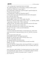
1. The working mode of speed and location are similar. The variable declaration area of the program is defined as follows speed1 at%Q0.0:int; (*Define the 1st speed signal *) pos1 at%Q2.0:dint; (*Define the 1st position signal *) speed2 at%Q6.0:int; (*Define the 2nd speed signal *) pos2 at%Q8.0:dint; (*Define the 2nd position signal *) (1) First call the motor pulse initialization function block in the program: EXT_MOTOR_PWM_INIT EN_IN: Function block enable signal NETNUMBER: Number of GC-2302 modules from PLC MOTOR_CH: the pulse output number of the gc-2302, 1 or 2 MOTOR_MODE: 1 speed mode;...
Open the catalog to page 8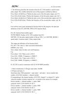
2. The following describes the situation when the GC-2302 module is used for pure pulse output: The variable declaration area of the program is defined as follows: Pwm_Duty1 at%Q0.0:int; (*Define the duty cycle of the first pulse output, unit %*) Pwm_FQ1 at%Q2.0:dint; (*Define the frequency of the first pulse output, unit: Hz* ) Pwm_Duty2 at%Q6.0:int; (*Define the duty cycle of the second pulse output, unit %*) Pwm_FQ2 at%Q8.0:dint; (*Define the frequency of the second pulse output, unit: Hz *) First call the motor pulse initialization function block in the program: the input pin definition of...
Open the catalog to page 9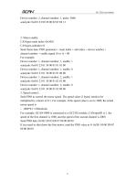
2. Motor enable: CANopen main index=0x3001 CANopen subindex=0 Send frame data: PDO parameter + main index + sub index + device number + channel number + enable signal (0 or 1) + 00 For example: Device number: 1, channel number: 1, enable: 1 send pdo: 0x601 23 01 30 00 01 01 01 00 Device number: 1, channel number: 1, enable: 0 send pdo: 0x601 23 01 30 00 01 01 00 00 Device number: 1, channel number: 2, enable: 1 send pdo: 0x601 23 01 30 00 01 02 01 00 Device number: 1, channel number: 2, enable: 0 send pdo: 0x601 23 01 30 00 01 02 00 00 3. Speed control: Send PDO to control the motor speed. The...
Open the catalog to page 10
3. Technical Specifications Interface characteristics Number of inputs Pulse voltage Electrical isolation Counter bit Installation position Power supply Environmental testing Operating temperature Permissible relative Humidity EMC test Vibration/shock Resistance EMC resistance burst/ ESD Protection class Basic information Dimensions Weight 2 5V 500 V(GC-bus/ Signal voltage) 32-bit In sequential order Powered by GCAN-PLC series, current consumption 50mA -40℃~+85℃ 95%RH,no condensation EN 55024:2011-09 EN 55022:2011-12 EN 60068-2-6/EN 60068-2-27/29 EN 61000-6-2 /EN 61000-6-4 IP 20 100mm *69mm *12mm...
Open the catalog to page 11
4. Disclaimer Thank you for purchasing GCAN's GCAN series of hardware and software products. GCAN is a registered trademark of Shenyang Vhandy Technology Co., Ltd. This product and manual are copyrighted by Vhandy Technology. Without permission, it is not allowed to reproduce in any form. Before using, please read this statement carefully. Once used, it is deemed to be an endorsement and acceptance of the entire content of this statement. Please strictly abide by the manual, product description and related laws, regulations, policies and guidelines to install and use the product. In the process...
Open the catalog to page 12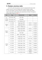
5. Module selection table GCAN-PLC-400 series products consist of a programmable main control module, several GC series IO modules and a terminal resistance module. GC series IO modules currently include five categories: digital input, digital output, analog input, analog output, and communication extension. The specific selection table is shown in Table 5.1. I/O relay output Voltage input, 16 bits Voltage input, 16 bits Digital input Current input, 16 bits Current input, 16 bits Voltage input, 16 bits Voltage input, 16 bits Thermal resistance Thermal resistance
Open the catalog to page 13
Voltage output, 16 bits Voltage output, 16 bits Current output, 16 bits Current output, 16 bits Voltage output, 16 bits Voltage output, 16 bits Voltage output, 12 bits Special module Analog output K type / S type / T type thermocouple GPRS extension WiFi extension Table 5.1 Selection table
Open the catalog to page 14
Sales and service Shenyang Vhandy Technology Co., Ltd. Address: Room 401, D11 Block, SISP., Hunnan District, Shenyang, Liaoning, China E-mail: [email protected] Tel/ Whatsapp: +86-13644001762 Website: gcanbus.com
Open the catalog to page 15All Shenyang Vhandy Technology Co. catalogs and technical brochures
 GC-8012 Power Supply Module
12 Pages
 GC-2204-4 Channel Relay Output
13 Pages
 GC-2018-8DO(NPN)
13 Pages
 GC-2008-8DO(PNP)
13 Pages
 GC-1502-2Channel Counter Module
13 Pages
 GC-1018-8DI(NPN)
13 Pages
 GC-1008-8DI(PNP)
13 Pages
 GCAN-IO-8100
20 Pages
 GCAN-IO-8000
25 Pages
 GCAN-PLC-511
31 Pages
 GCAN-PLC-510
31 Pages
 GCAN-PLC-400
31 Pages


