 Website:
Shaw Moisture Meters
Catalog excerpts

Model SDT-Ex Dewpoint Transmitter Instruction Manual Issue 1.2.1
Open the catalog to page 1
EU Declaration of Conformity We Of Declare that Model Name: Shaw Moisture Meters Len Shaw Building, Bolton Lane, Bradford, England, BD2 1AF The SDT-Ex is an intrinscally safe 3 wire 4-20 mA loop powered transmitter SDT-Ex Intrinsically Safe 4-20 mA Dewpoint Transmitter Ex II 1 GD Ex ia IIC T4 Ga (-20 °C ≤ Ta ≤ +60 °C) Ex ia IIIC T200135°C Da (-20 °C ≤ Ta ≤ +60 °C) Conforms to the following directives: 2014/34/EU ATEX Directive 2014/30/EU The Electromagnetic Compatibility Directive And designed and manufactured to the following standards: EN IEC 60079-0:2018 Electrical apparatus for...
Open the catalog to page 2
UK Declaration of Conformity We Of Declare that Model Name: Shaw Moisture Meters Len Shaw Building, Bolton Lane, Bradford, England, BD2 1AF The SDT-Ex is an intrinscally safe 3 wire 4-20 mA loop powered transmitter SDT-Ex Intrinsically Safe 4-20 mA Dewpoint Transmitter Ex II 1 GD Ex ia IIC T4 Ga (-20 °C ≤ Ta ≤ +60 °C) Ex ia IIIC T200135°C Da (-20 °C ≤ Ta ≤ +60 °C) Conforms to the following directives: Equipment and Protective Systems Intended for use in Potentially Explosive Atmospheres Regulations 2016:1107 Electromagnetic Compatibility Regulations 2016:1091 And designed and manufactured...
Open the catalog to page 3
1.0 Unpacking your Shaw Moisture Meters Model SDT-Ex Please examine the SDT-Ex package for any damage or mishandling. If any damage is evident please notify the carrier and the Shaw Moisture Meters representative from where this unit was purchased. You should have received (if ordered): ● 1 SDT-Ex 4-20 mA dewpoint transmitter ● 1 connecting cable, 2m as standard (or length specified on your order) ● 1 SDT-Ex special sensor holder ● 1 instruction manual ● 1 pressure dewpoint circular calculator If anything is missing please contact your distributor immediately. 1.1 General Description The...
Open the catalog to page 5
The SDT-Ex transmitter can withstand 35,000 kPa (350 bar) maximum pressure and by employing low resistance cable. The transmitter can be located at significant distances, in excess of 1,000 metres from the data collection point. Designed with the operator in mind, for reliable and accurate measurements, the SDT-Ex transmitter is extremely easy to install and operate, requiring little or no maintenance. 2.0 Gas Compatibilities The sensing elements of the SDT-Ex transmitter are Al2O3 and therefore suitable for many different industrial and research applications. Most gases can be checked for...
Open the catalog to page 6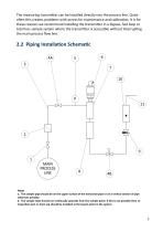
The measuring transmitter can be installed directly into the process line. Quite often this creates problems with access for maintenance and calibration. It is for these reasons we recommend installing the transmitter in a bypass, fast loop or total loss sample system where the transmitter is accessible without interrupting the main process flow line. 2.2 Piping Installation Schematic 4A MAIN PROCESS LINE Notes a. The sample pipe should be on the upper surface of the horizontal pipe or on a vertical section of pipe wherever possible. b. The sample tube should run continually upwards from...
Open the catalog to page 7
2.3 Piping Schematic Component Index 1. 2. Sample Isolation Valve - A recommended item as it allows access to the sample system without interrupting the main process line. Filter Unit - Recommended when the samples are likely to contain particulate matter. If the air/gas sample contains heavy hydrocarbon condensate, the filter must be of the coalescing type with a drain. The filter unit should be positioned as close to the sample point as practical. Sample Tube - This should be stainless steel for dry air or gas applications but copper or carbon steel can be used where wetter gases are to...
Open the catalog to page 8
2.4 Installing and Commissioning the SDT-Ex Transmitter It is advisable to carry out an initial purge routine of the sample loop before installing the transmitter in order to remove the possibility of sensor damage on start-up. Refer to the sample schematic in section 2.2 Piping Installation Schematic. Open the inlet isolation valve slowly, until a small flow of air/gas at atmospheric pressure flows through the inlet pipe work to the transmitter holder and exhausts through the sensor entry port of the transmitter holder. Allow this purge to continue for approximately 15-20 minutes. This is...
Open the catalog to page 9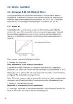
3.0 Normal Operation 3.1 Analogue 4-20 mA Mode (3 Wire) In normal operation, the transmitter will produce a 4-20 mA signal, which is proportional to the level of moisture in the gas being monitored. The moisture reading is sampled and updated once per second. The SDT-Ex has 3,020 distinct steps over the 4-20 mA range corresponding to a resolution of 0.005 mA. 4.0 AutoCal AutoCal allows the user to ensure accuracy to the laboratory calibration by checking the span of the transmitter and correcting for any deviation. It should be operated periodically, every two to three months or can be used...
Open the catalog to page 10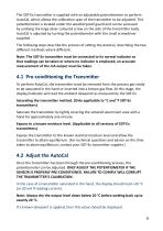
The SDT-Ex transmitter is supplied with an adjustable potentiometer to perform AutoCal, which allows the calibration span of the transmitter to be adjusted. This potentiometer is located under the weatherproof guard and can be accessed by undoing the large silver coloured screw on the side of the transmitter body. AutoCal is adjusted by turning the potentiometer with the small screwdriver supplied. The following steps describe the process of setting the AutoCal, describing the two different methods where different. Note: The SDT-Ex transmitter must be connected to its normal indicator so...
Open the catalog to page 11
4.3 Completing the AutoCal Once the desired value is reached and the AutoCal process is complete, remove the screwdriver from the potentiometer and replace the weatherproof guard, fasten using the large silver coloured screw. If using the saturated transmitter method, the transmitter can be put down on a work bench. The SDT-Ex transmitter will now output the corrected dewpoint and can be reinserted into the process. ● If the sensor is short-circuited, the transmitter will produce a constant 20.75 mA output. ● If the sensor is open-circuited, the transmitter will produce a constant 20.50 mA...
Open the catalog to page 12


