- Catalogs
- Shaw Moisture Meters
- AcuVu Inline Hygrometer Instruction Manual
- Company
- Products
- Catalogs
- News & Trends
- Exhibitions
AcuVu Inline Hygrometer Instruction Manual
1 /15Pages

AcuVu Inline Hygrometer Instruction Manual
1 /15Pages
Catalog excerpts

Single Channel Inline Hygrometer Instruction Manual Issue 1
Open the catalog to page 1
1 Unpacking your Shaw Moisture Meters AcuVu Please examine the AcuVu for any damage or mishandling. If any damage is evident please notify the carrier and the Shaw Moisture Meters representative from where this unit was purchased. You should have received (if ordered): ● ● ● 1 AcuVu instrument 1 instruction manual 1 pressure dewpoint circular calculator If anything is missing please contact your distributor immediately. 2 General Information Digital display of current, 4-20 mA output from the transmitter Increase the numerical value or choose the next parameter Accept the chosen value and end...
Open the catalog to page 3
3 Safety Information Read the safety information BEFORE installation. 3.1 Warning This device is designed for connection to hazardous electric voltages. To avoid the risk of electric shock and fire, the safety instructions of this manual must be observed and followed. Hazardous voltages may be present on instrument terminals. The equipment must be installed by suitably qualified personnel and the instrument must be mounted in a position that provides protection behind the panel to at least IP20. When mounted in front panels, the included rubber packing must be mounted between the panel cut-out...
Open the catalog to page 4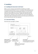
4 Installation 4.1 Installing the Instrument to the Panel Make a cut-out in the donor panel 92.0/92.8 x 45.0/45.6 mm (⅛ DIN). The maximum panel thickness is 10 mm. If an effective IP65 weatherproof seal is required, the minimum recommended panel thickness is 1.6 mm. Pass the instrument case through the cut-out in the donor panel and slide the panel clamp over the instrument from the back. Tighten the retaining screws until the instrument is clamped securely in position. The screws must be tightened sufficiently to affect a seal between the front of the donor panel and the back of the instrument...
Open the catalog to page 5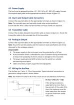
4.3 Power Supply The AcuVu can be powered by either a 22 - 253 V AC or 20 - 300 V DC supply. Connect the required supply cable to the appropriate terminals as shown in figure 1.1. 4.4 Alarm and Output Cable Connectors Connect the required cables to the appropriate terminals as shown in figure 1.1. Note: The normally open and normally closed relay contact positions. Ensure that the wire is fully inserted and that no loose strands are exposed. 4.5 Transmitter Cable Connect the AcuDew dewpoint transmitter cable as shown in figure 1.1. Route the transmitter cable to the intended site of the transmitter....
Open the catalog to page 6
5 Default Instrument Configuration When configuring the display, you are guided through all parameters. You can choose the settings which suit the application. For each menu there is a scrolling help text which is automatically shown in the display. This starts after five seconds if no key has been activated. Configuration is carried out by using the three function keys: Will increase the numbered value or choose the next parameter. Will decrease the numerical value and choose the previous parameter. Will accept the chosen value and end the menu. Once the configuration has been entered the display...
Open the catalog to page 7
7.3 PASS The PASS option allows the user to alter the security password used to protect the setup menu. Whilst PASS is displayed use and keys to enter the subroutine. The instrument now displays 0000. Use and keys to enter the new password. Press . 7.4 AL1 and AL2 The AL1 and AL2 option allows the user to set up two independent alarms. Trip point, direction of trigger’ relay enable status, latching status and hysteresis can be set within this option. To activate the quick alarm settings screen, press or . The LED now displays ‘F.SET’ followed by a selection menu for AL1 or AL2 relay. Using the...
Open the catalog to page 8
8 Normal Operation of the AcuVu In normal operation, the AcuVu will display the current moisture value of the connected transmitter. The value is displayed in the currently selected engineering units, which is indicated by the small LED and updated once per second. The alarm LEDs (AL1 and AL2) will light whenever an alarm condition occurs and only turn off when the alarm condition clears. Remote signalling of an alarm condition is provided by two internal changeover relays that trigger at the same time as the LEDs. 9 Faults/Errors If the sensor is short-circuited, the transmitter will produce...
Open the catalog to page 9
11 Specification Electromagnetic Compatibility (EMC) Low Voltage Directive EMC Directive 2004/108/EC Complies with BS EN 61326 73/23/EEC EN 61010-1 Power Consumption Alarm Relays Two independent fully programmable switched contacts. Rated 2 A @ 250 V AC/ 1 A @ 24 V DC AL1 and AL2 LEDs on front panel indicate status of each alarm Alarm & Range Limits °C dewpoint °F dewpoint P (ppm) b (ppb) L (lb/MMSCF) Output Signal Linear 4-20 mA or 0-20 mA fully isolated Isolation Voltage, Test/ 2.3 kV AC / 250 V AC Operation Operating Voltage Operating Pressure From 1 kPa (0.01 barA) to maximum 35,000 kPa (350...
Open the catalog to page 10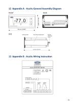
12 Appendix A - AcuVu General Assembly Diagram FRONT Sealing Gasket Panel Mounting Bracket Bracket Retaining Screw 13 Appendix B - AcuVu Wiring Instruction
Open the catalog to page 11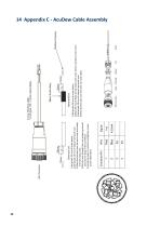
1) Strip back 25 mm of outer sleeve. 2) Strip back 10 mm of sleeve from each core. 3) Place the ferrules over the wire core and solder, trim the excess wire. 4) Put the wire through the nut, gripper, grommet and into the body of the connector. 5) Locate Ferrules in contacts and tighten screws as per table below. 1) Strip back 25 mm of outer sleeve. 2) Place 30 mm of Black shrink sleeve over outer sleeve, overlap 2 inner cores. 3) Strip back 10 mm of sleeve from each core. 4) Place the Ferrules over the wire core and solder. 14 Appendix C - AcuDew Cable Assembly
Open the catalog to page 12
15 Appendix D - Default Instrument Configuration The AcuVu is configured to default factory settings. To review or alter the settings, please see table below. Configuration Configuration is carried out using the three function keys. will increase the numerical value or choose the next parameter. will decrease the numerical value or choose the previous parameter. will accept the chosen value and end the menu. Contains submenus as follows. The defaults are: • Setting 4-20 mA range (high/low) • Decimal point • Alarm 1 • Alarm 2 • Analogue output settings Sensor Range The span is set to the full...
Open the catalog to page 13All Shaw Moisture Meters catalogs and technical brochures
 Superdew 3 WP Instruction Manual
28 Pages


- Flowmeter
- Volume flow monitor
- Industrial display panel
- Pressure gauge
- Pressure limiter
- Gas flow monitor
- Single-stage pressure regulator
- Stainless steel flow monitor
- Industrial pressure limiter
- Analog pressure gauge
- LED display panel
- Electronic display panel
- Filter housing
- Dial pressure gauge
- Programmable display system
- Gas pressure limiter
- Cartridge filter housing
- Industrial printer
- Bourdon tube pressure gauge