
Catalog excerpts

Model AcuDew Dewpoint Transmitter Instruction Manual Issue 1
Open the catalog to page 1
1.0 Unpacking Your Shaw Moisture Meters AcuDew Please examine the AcuDew package for any damage or mishandling. If any damage is evident please notify the carrier and the Shaw Moisture Meters representative from where this unit was purchased. You should have received (if ordered): ● 1 AcuDew 4-20 mA dewpoint transmitter ● 1 connecting cable of the length specified on your order or two metres as standard ● 1 instruction manual ● 1 pressure dewpoint circular calculator ● 1 small screwdriver If anything is missing please contact your distributor immediately. 1.1 General Description The Shaw...
Open the catalog to page 4
The RISC microprocessor circuitry of the Model AcuDew transmitter allows high resolution with advanced self-diagnostics for fault conditions. It also enables periodic recalibration of the dewpoint sensor, storing calibration data within the fully self-contained unit. Loop powered, by a 7 to 28V DC source, the Model AcuDew transmitter will provide the user with a linear 4-20 mA signal over the chosen range. The mechanics of the Model AcuDew transmitter have been designed to cope with extreme environmental conditions. The rugged stainless steel construction offers protection to IP66 (NEMA...
Open the catalog to page 5
2.0 Gas Compatibilities The Model AcuDew sensing elements are Al2O3 and therefore suitable for many different industrial and research applications. Most gases can be checked for their moisture content with no need for the calibration to be altered when changing between different gases, as the sensor operates only with reference to the water vapour content. However, some gases must be avoided, as they are not compatible with the material used in the construction of the sensor. Ammonia (NH3) and Chlorine (Cl2) must be avoided at all times, even in small quantities. Hydrogen Chloride (HCl)...
Open the catalog to page 6
2.1 Installing the AcuDew in an Air/Gas Sampling System The piping installation schematic diagram shows all components, which could be used in a gas measurement application. Not all items shown will be required for every installation. The flow rate, although not critical, should be low enough to avoid abrasion to the sensor surface without being so low as to extend the system response time to an unacceptable level. In general, a flow rate of between two and three litres/min at normal temperature and pressure, will give the right balance. The sensor is a variable capacitor, which is directly...
Open the catalog to page 7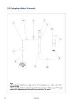
2.2 Piping Installation Schematic MAIN PROCESS LINE Notes a. The sample pipe should be on the upper surface of the horizontal pipe or on a vertical section of pipe wherever possible. b. The sample tube should run continually upwards from the sample point. If this is not possible then an inspection port or drain tap should be installed at the lowest point in the system.
Open the catalog to page 8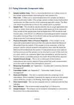
2.3 Piping Schematic Component Index 1. 2. Sample Isolation Valve - This is a recommended item as it allows access to the sample system without interrupting the main process line. Filter Unit – A filter unit is recommended when the samples are likely to contain particulate matter. If the air/gas sample contains heavy hydrocarbon condensate, the filter must be of the coalescing type with a drain. The filter unit should be positioned as close to the sample point as practical. Sample Tube – This should be stainless steel for dry air or gas applications but copper or carbon steel can be used...
Open the catalog to page 9
2.4 Installing and Commissioning The AcuDew dewpoint transmitter can be installed in three general ways: 1. Directly in to the process line. 2. As part of a sample conditioning system using a Shaw Moisture Meters sensor holder. 3. Using the AcuLoop display module. Before installing the dewpoint transmitter, it is advisable to carry out an initial purge routine of the sample loop in order to remove the possibility of sensor damage on start-up. Refer to the sample system schematic in section 2.2. Open the inlet isolation valve slowly, until a small flow of air/gas at atmospheric pressure...
Open the catalog to page 10
3.0 Connecting the AcuDew Connector Pins 3.1 AcuDew 4 - 20 mA Cable Assembly The cable assembly consists of a M12 5 pin cable connector used in conjunction with a 2 core 7/0.2 mm cable. Details of wiring can be found in Appendix D. 3.1.1 Connecting the AcuDew Cable Align the keyed groove in the connector with the keyed notch in the AcuDew, push inwards and screw the locking ring clockwise finger tight. 3.1.2 Connecting the AcuLoop To connect the AcuLoop display to the AcuDew: 1. Disconnect the connector from the AcuDew by turning the locking ring counter-clockwise. 2. Screw this connector...
Open the catalog to page 11
3.1.3 Connecting the AcuDew to an AcuTrak The AcuTrak displays a digital readout of the 4-20 mA input signal derived from an attached AcuDew. The AcuTrak indicator has: • A five digit, red LED display, relay ON/OFF indication. • Process control with two adjustable alarm set points. • An analogue output. • RS485 serial communications. Alarm set points can be adjusted via the keys on the front panel. mA+ = BLUE WIRE 24 V = RED WIRE MAINS POWER SUPPLY 3.2 Wiring the AcuDew The AcuDew is a 2-wire, 4-20 mA transmitter. Typical electrical connection to generate a voltage output is shown below....
Open the catalog to page 12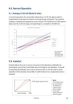
4.0 Normal Operation 4.1 Analogue 4-20 mA Mode (2-wire) In normal operation, the transmitter will produce a 4-20 mA signal, which is proportional to the level of moisture in the gas being monitored. The moisture reading is sampled and updated once per second. The AcuDew has 3,020 distinct steps over the 4-20 mA range corresponding to a resolution of 0.005 mA. Conversion: mA to Range (°C) 40.0 20.0 Purple Silver See section 9.2 Appendix B Conversion Table: mA to Range (°C) 5.0 AutoCal AutoCal allows the user to ensure accuracy to the laboratory calibration by checking the span of the...
Open the catalog to page 13
5.1 Pre-conditioning the Transmitter To perform AutoCal, the transmitter needs to be removed from the process gas at which point the display/indicator will read the ambient dewpoint or full scale (if the ambient dewpoint level is above the range of the AcuDew). Expose the transmitter to the known AutoCal moisture level and allow the transmitter to attain equilibrium. (For technical questions and advice on the time taken to attain equilibrium contact your AcuDew supplier.) Method 1: Expose to a known moisture level (Applicable to all versions of AcuDew transmitters.) If a known gas is...
Open the catalog to page 14


