- Catalogs
- SHAREBOT SRL
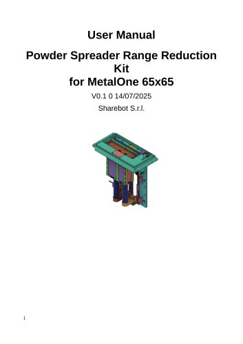
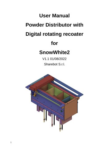
- User Manual Reduced Area Powder Distributor
User Manual Reduced Area Powder Distributor
1 /13Pages
User Manual Reduced Area Powder Distributor
1 /13Pages
Catalog excerpts

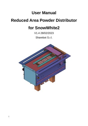
User Manual Reduced Area Powder Distributor for SnowWhite2 V1.4 28/02/2023 Sharebot S.r.l.
Open the catalog to page 1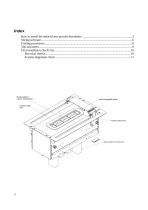
Interchangeable blade Building platform volume: 40x60x60mm Double loading tank Powder outlet funnel Used powder recovery tank
Open the catalog to page 2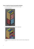
How to install the reduced area powder distributor: 1. Turn off the printer and disconnect from the power supply; 2. Remove the front door; 3. Remove the gaskets of the upper and lower compartment; 4. Unscrew (without removing them) the n°4 M6 screws that fix hooks on the right of the printer;
Open the catalog to page 3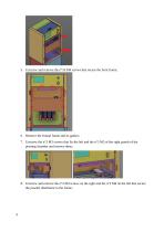
5. Unscrew and remove the n°16 M4 screws that secure the front frame; 6. Remove the frontal frame and its gasket; 7. Unscrew the n°3 M3 screws that fix the left and the n°3 M3 of the right panels of the printing chamber and remove them; 8. Unscrew and remove the n°2 M4 screws on the right and the n°2 M4 on the left that secure the powder distributor to the frame;
Open the catalog to page 4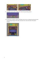
9. If installed, unscrew the n°2 M4 screws that fix the gas heating resistor; 10. At this point is possible to slide the distributor forward a few centimeters and proceed with disconnecting the plugs of the cables connected to the wall on the back of the printer chamber;
Open the catalog to page 5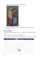
11. Remove the powder distributor from the printer chamber; 12. Now is possible to follow in reverse the same operation to install the new powder distributor; Slicing software: The suggested and supported slicing software to use with the reduced area powder distributor is Cura. The machine profile is: “Reduced Printing Area SnowWhite2” About materials profile and printing profile is possible to use the original SnowWhite2 profiles.
Open the catalog to page 6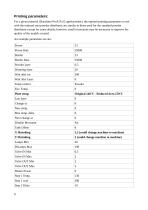
For a given material (Duraform ProX Pa12 aged powder), the optimal printing parameters to use with the reduced area powder distributor are similar to those used for the standard powder distributor except for some details; however, small corrections may be necessary to improve the quality of the models created.
Open the catalog to page 8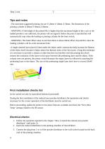
Tips and notes - The maximum suggested printing size are X 20mm Y 40mm Z 50mm. The dimension of the printing cylinder X 40mm Y 60mm Z 60mm; - WARNING: If the height of the printed file is higher than the maximum height of the z axis or the loaded powder is not sufficient, the printer will not signal it before the print is launched but will automatically stop when the loading or printing cylinder hit the limit switch; - WARNING: The Tank Offset value is real from 0mm to about 50mm offset, beyond this value the loading cylinders will be at the maximum limit; -A single sintered layer placed 0.3mm...
Open the catalog to page 9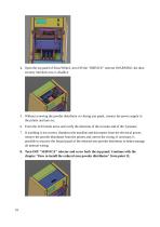
Open the top panel of SnowWhite2, turn ON the "SERVICE" selector (WARNING: the door security interlock now is disable); 5. Without screwing the powder distributor or closing any panel, connect the power supply to the printer and turn on; 6. From the LCD menu move and verify the direction of the recoater and of the 3 pistons; 7. If anything is not correct, shutdown the machine and disconnect from the electrical power, remove the powder distributor from the printer and correct the wiring. If necessary is possible to unscrew the frontal panel of the reduced area powder distributor to better manage...
Open the catalog to page 10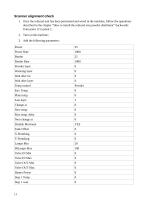
1. Once the reduced unit has been positioned and wired in the machine, follow the operations described in the chapter “How to install the reduced area powder distributor” backwards from point 12 to point 1;
Open the catalog to page 11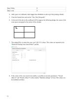
4. Add a piece of cardboard a little bigger than 40x60mm on the top of the printing cilinder; 5. Close the frontal door and run the “Test_Dist_Rid.gcode” 6. At the end of the job on the cardboard will be engrave the following design, the center of the cross must correspond to the center of the cylinder: 7. The original file, to center the cross, use X-40 Y-31 values. This values are reported in the “Reduced Printing Area SnowWhite2” profile; 8. If the center of the cross need to be modify, is possible to tune this parameters: “Nozzel offset X” and “Nozzle offset Y” in the window “Machine settings”...
Open the catalog to page 12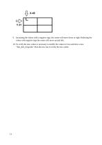
9. Increasing the values with a negative sign, the center will move down or right. Reducing the values with negative sign the center will move up and left; 10. To verify the new values is necessary to modify the values in Cura and slice a new "Test_dist_rid.gcode". Run the new test to verify the new center.
Open the catalog to page 13All SHAREBOT SRL catalogs and technical brochures
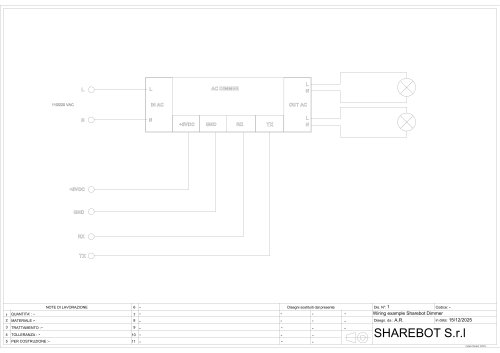 Dimmer wiring diagram
1 Page
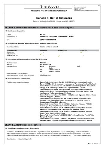 SDS Finishxpert Filler
30 Pages
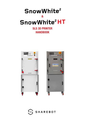 Snowwhite2 Handbook
40 Pages
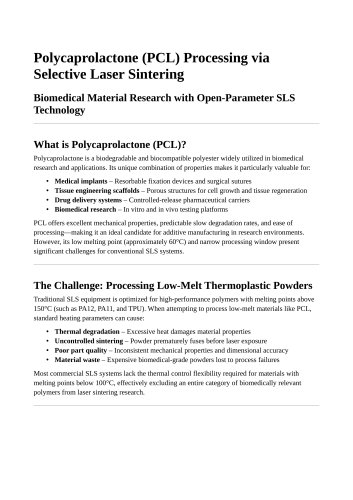 Snowwhite2 PCL
4 Pages
 Snowwhite2 enduser patent report
25 Pages
 Snowwhite2 Temperature LOG
3 Pages
 Snowwhite2 brochure
2 Pages
 Snowwhite2 User Manual
49 Pages
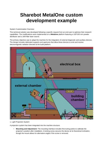 Metalone custom development
2 Pages
 Metalone User Manual
73 Pages
 Metalone brochure
2 Pages
 Metalone Handbook
28 Pages
 User Manual Snowwhite2HT
44 Pages
 Brochure Snowwhite2HT
2 Pages
- Additive manufacturing machine
- Automatic test kit
- Industrial 3D printer
- Plastic additive manufacturing machine
- High-performance 3D printer
- FDM 3D printer
- Laboratory test kit
- Prototyping 3D printing machine
- High-speed 3D printer
- Plastic spray
- Metal 3D printing machine
- Large-format 3D printer
- ABS 3D printer
- Polyester sealant
- PLA 3D printer
- Medical 3D printing machine
- Desktop 3D printer
- Dental additive manufacturing machine
- PA 3D printer
- 3D printer for the aerospace industry