ZCT-CX300
1 /18Pages

ZCT-CX300
1 /18Pages
Catalog excerpts
ZCT-IPI-DC01 Datalogger Configuration Manual
Open the catalog to page 1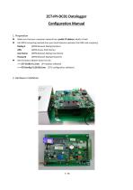
ZCT‐IPI‐DC01 Datalogger Configuration Manual 1. Preparation Make sure that your computer network has a public IP address, which is fixed. Get GRPS connecting method from your local telecoms operator (the SIM card company): Dialing # (GPRS Network Dialing Number) (GPRS Access Point Name) User Name Password (GPRS Network Dialing User Name) (GPRS Network Dialing Password) Get the latest software tools from ZC: >>> ZCT‐CX100 V1.3.exe (IPI readout software) >>> DTUConfig V1.
Open the catalog to page 2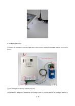
3. Configuring the DTU 3.1 Connect the datalogger to your PC using RS‐485 to USB converter, keeping the datalogger powered off during the process. 3.2 Turn off firewall and anti‐virus software on your PC. 3.3 Open the DTU configuration software tool (DTUConfig) on your PC,
Open the catalog to page 4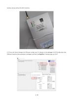
minutes, and you will see the LED’s turned on. 3.4 Find at the Device Manager the COM port number your PC allocates to the datalogger. On DTUConfig select that COM port, keep the other parameters unchanged, and then click OpenPort
Open the catalog to page 5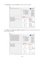
3.5 Click ReadConfig and set BaudRate to 9600 (do not change the others), then click Set. 3.6 Click GPRS and input Dialing #, APN, UserName and Password (must be correct!), according to instructions of your SIM card
Open the catalog to page 6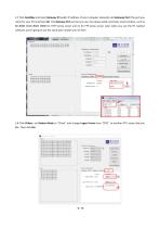
3.7 Click GateWay and input Gateway IP (public IP address of your computer network) and Gateway Port (the port you name for your PC) and then Set. The Gateway Port can be any one, but please avoid commonly used numbers, such as 80 /8080 /3128 /8081 /9080 for HTTP proxy server and 21 for FTP proxy server. Later when you use the IPI readout software, you’re going to use the same port number you set here. 3.8 Click Others, set Station Mode to “Client” and change
Open the catalog to page 7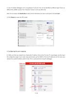
In case of multiple dataloggers set to one gateway IP and port, they can be identified by different logon frame (i.e. different DTU_NAME: xxxxxxx). The 7 character “xxxxxxx” can be any ASCII code. Note: You can always click ReadConfig to make sure the information you input is well saved in the datalogger. 3.9 Click Reboot to restart the DTU modle. 4. Configuring the port mapping 4.1 Make sure that your network has a fixed public IP address: find out the IP of your PC using Google, and then log in the configuration page of your router using web browser, get the WAN IP, if the two IP addresses...
Open the catalog to page 8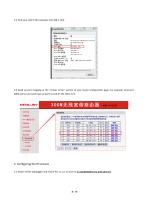
4.2 Find your LAN IP (for example, 192.168.1.123). 4.3 Build up port mapping at the “virtual server” section of your router configuration page. For example, bind port 6006 (server port and internal port) to LAN IP 192.168.1.123. 5. Configuring the IPI sensors 5.1 Power off the datalogger and rewire Pin 11, 1
Open the catalog to page 9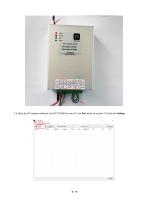
5.2 Open the IPI readout software tool (ZCT‐CX100) on your PC, Set Port (refer to section 3.7) and click Set
Open the catalog to page 10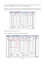
5.3 Power on the datalogger, and then waiting for their building up connection. When they are connected, the SIM and Status LED on the datalogger blink slowly at the same pace. Power off the datalogger. 5.4 Connector one sensor probe to one of the two input channels of the datalogger using M14 cable. Power on the datalogger, set DTU name, select channel, read old address and set new address (if necessary). Refer to below drawing: Repeat the procedure for the other sensor probes. If
Open the catalog to page 11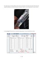
The original (pre‐set at factory) address of each sensor can be found on the body of the probe. Both decimal and hexadecimal addresses are printed on the label. For example, “01 (0x)” or “01, 0x” indicates that it is sensor number 1. 5.5 Set datalogger RTC time and turn on automatic timing
Open the catalog to page 12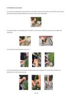
6. Installing the sensor probes 6.1 Connect the waterproof connector terminal to the cable connector at the shorter end of the first probe, with the fixed wheel facing the expected displacement direction of the measured borehole. 6.2 Hang the probe on the wellhead with a screwdriver or other tools, install the connecting rod, and tighten the locking bolt. 6.3 Connect the remaining probes one by one. 6.4 The last probe (the top one) should be connected to the steel s
Open the catalog to page 13
CAUTION: 1. The fixed wheel of the probe shall be installed towards the expected displacement direction of the measured borehole. 2. The cable connector joints between probes shall be locked with spanner to prevent water from entering. 3. In case the cables are longer than needed, they can be fixed on the connecting rods with cable ties so the probes will not get stuck when they are lowered into the measured borehole. 4. While lowering, lifting or fixing the probes, please hold the probe body or the rescue wire and do not hold or pull the cables hard. 7. Data browsing and query on voltage/temperature...
Open the catalog to page 14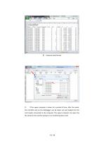
B) Autosave data format C) If the upper computer is down for a period of time, after the repair, the microSD card on the datalogger can be taken out and loaded into the card reader connected to the computer. The upper computer can open the file stored in the card f
Open the catalog to page 15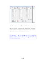
D) Upper computer reading datalogger power supply voltage and temperature Note: The more sensors are connected in the acquisition system, the longer the time for all angle data of the entire system to be updated once. The approximate acquisition time for a system with 32 sensor probes is 1 minute. This information in this manual is for reference only. Shanghai Zhichuan Electronic Tech Co., Ltd.
Open the catalog to page 16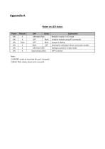
Alternate flash OFF Blink OFF Blink Blink OFF Alternate blink Synchronous blink Note: 1) ON/OFF: shine or not shine for over 3 seconds. 2) Blink: flash slowly, about once a second. Explanation Module is open, in AT mode Initialize module using AT commands System is dialing Waiting for activation
Open the catalog to page 17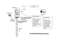
Internet SIM card slot Antenna Upper PC #DTU module inside Port 1, 2: Power supply Port 11, 12 (Datalogger COM) and Port 13, 14 (DTU Module COM): RS-485 Modbus # Data collection To configure, connect Port 13, 14 to your PC DTUconfig.exe installed
Open the catalog to page 18All Shanghai Zhichuan Electronic Tech Co., Ltd catalogs and technical brochures
 ZCT330M1-LWP-AN-YKG
20 Pages
 ZCT-CX09
10 Pages
 ZCTR04
4 Pages
 ZCTXXXK-LPS-155
4 Pages
 ZCT190J-LPS-A
3 Pages
 ZCT190J-LNS-20
3 Pages
 ZCT190AL-V1
5 Pages
 ZCT181J-LMS
3 Pages
 ZCT1XXX-LNX-140
3 Pages
 ZCT2XXL-XXS-A-7X
9 Pages
 ZCT1XXXJ-SXX-1907
2 Pages
 ZCT190J-SPS-A
6 Pages
 ZCT290RS-LPS-77
5 Pages
 ZCT1000ML-S230
4 Pages
 ZCT330Ex-SWP-N-YK
4 Pages
 ZCT215L-SQS-A1B-1907
4 Pages
 ZCT175J-NMQ
4 Pages
 ZCT145KR-LQS-AH-6207
4 Pages
 ZCT21B0J-LPS-A
4 Pages


- Data logger
- Communication gateway
- Tilt sensor
- Datalogger without display
- Wireless gateway
- Digital inclination sensor
- 2-axis tilt sensor
- MEMS inclination sensor
- Multi-axis tilt sensor
- Analog inclination sensor
- High-precision tiltmeter
- 1-axis tilt sensor
- IP67 inclination sensor
- Digital datalogger
- Rugged inclination sensor
- Tilt switch
- High-resolution inclinometer
- RS-485 datalogger
- RS-485 inclinometer
- Waterproof tiltmeter