
- Catalogs
- SHANGHAI STEP ELECTRIC CORPORATION
- K/iK series AC Servo Driver


K/iK series AC Servo Driver

K/iK series AC Servo Driver
This manual is designed for users of the K/iK series AC servo drivers, emphasizing the importance of thorough reading before use and keeping it for future reference. Users are encouraged to contact technical support for any questions regarding the product's functions or performance.
Users must adhere to safety guidelines to prevent electric shock, equipment damage, and fire hazards. Key points include avoiding opening the casing when powered on, ensuring proper grounding, not connecting power directly to certain terminals, and installing the driver in a safe environment.
The manual is structured into several chapters, each focusing on different aspects of the servo driver, including function overview, installation, wiring, panel operation, and operation procedures.
Important procedures include ensuring proper installation direction, following specific wiring diagrams, and conducting trial operations to verify system functionality.
Users are advised to regularly check and maintain the servo driver, use compliant power supplies, and consult the manual for troubleshooting.
This chapter describes the models and basic functions of the servo driver and motor, including control modes, encoder feedback, and protection functions.
Emphasizes proper installation to avoid failures, detailing storage conditions, installation site requirements, and precautions against heat and vibration.
Covers electronic gear setting, torque control operation, speed control operation, and control mode selection.
Outlines wiring requirements and user parameters for communication, detailing the MODBUS protocol.
Provides methods for diagnosing and treating abnormalities, including alarm displays and their causes.
The servo driver should be installed vertically with adequate space for cooling, and the control cabinet's temperature should be even to prevent overheating.
Specifies temperature, humidity, and vibration conditions for optimal operation.
Details installation methods and precautions to avoid mechanical mismatch and ensure long service life.
Emphasizes the separation of power and signal lines to prevent malfunctions and the use of shielded wires for signal and feedback lines.
Provides detailed descriptions of terminal functions and wiring examples for various configurations.
Details wiring for position control mode and speed/torque control mode, emphasizing the need for shielded twisted pair cables.
Outlines signal definitions for the servo driver, focusing on connector terminals and output signals for position control systems.
Details communication connection terminal signal definitions for various series.
Recommends using specified cables and noise filters to prevent interference.
Describes basic panel operations, including key functions for switching displays and setting parameters.
Includes functions like software version display, jogging mode running, and load inertia identification.
Outlines steps for completing position demonstration operations and identifying inertia percentage.
Describes how to initialize user parameter setups and display history alarm data.
Details input signal distribution based on user parameter setup.
Provides a list of output circuit signal distributions and conditions for changes.
Outlines input and output signal specifications, including zero clamping action and encoder signal output.
Details pin configurations for encoder outputs and frequency dividing circuit.
Covers user parameter settings for position control via pulse train.
Explains the procedure for setting the electronic gear ratio.
Specifies user parameters for setting filter time constants.
Discusses suppression of low-frequency jitter in servo motors.
Stops reference counting input pulses during position control.
Managed through user parameters, with detailed instructions for adjustment.
Provides a speed limiting function to prevent excessive motor speed.
Describes internal set speed selection function.
Outlines signal timing for position control.
Provides methods for limiting output torque to protect machinery.
Supports various control modes, allowing shifts between different controls.
Describes servo alarm output signals and troubleshooting methods.
Supports data sets for parameter setting and communication setting.
Outlines various user parameters for configuring the servo driver.
Details input signals required for mode motion sequences.
Supports both incremental and absolute motion modes.
Procedures for returning to zero and seeking reference points.
Describes communication capabilities, including MODBUS communication.
Outlines the communication protocol for the servo driver.
Details communication addresses and command codes.
Structured in words with error checking using LRC and CRC.
Provides feedback through error frames with specific error codes.
Lists communication data addresses and their meanings.
Includes parameters for data sets, allowing for dynamic configuration.
Can be set to NULL, Absolute, or Relative for motion control strategies.
Defined by attributes like delay, pulse edge, and level of signal input.
Describes various servo operation statuses for monitoring and troubleshooting.
Explains the use of the "/V-CMP" signal for speed control.
The K/iK Series AC Servo Driver offers comprehensive control options through detailed parameter settings and communication protocols.
Focuses on abnormality diagnosis and treatment methods, including alarm displays and their causes.
Outlines the relationship between alarm displays and alarm code outputs.
Includes encoder disconnection, overload, overcurrent, overvoltage, and more.
Emphasizes correct wiring, appropriate cable specifications, and regular inspection.
Includes electronic gear faults, current detection abnormalities, and more.
Addresses bus encoder data issues and wiring interference.
Ensures proper connection and condition of regenerative resistors.
Addresses overheating and mismatches.
Includes servo motor start failures and control parameter issues.
Includes motor stops after surge, unstable motor rotation, and more.
Includes servo motor check, servo drive check, and replacement guidelines.
Includes vibration and sound checks, insulation resistance, and oil seal replacement.
Details parameter settings for user reference.
Outlines various input signal selections for different series.
Describes the distribution of output signals.
Details the source of pulse commands and analog voltage references.
Covers RS-485 communication settings.
Provides configurations for data sets.
Describes logic and level selection for input and output ports.
Indicates parameters not currently in use.
Emphasizes the importance of correctly setting signal distributions and communication parameters.
Catalog excerpts

AC Servo Driver User’s Manual
Open the catalog to page 1
● Thank you for purchasing this AC servo driver. ● This Manual is the user manual for K/iK series products. ● To use this series of servo drivers correctly, please carefully read this Manual before use and keep this Manual properly for future reference. If this product is purchased for your customer, please send this product to the final user together with this Manual. ☆ Warm tips: ◇ For the user who uses this product for the first time, please carefully read this Manual. If there is any question with the function or performance of this product, please contact our technical support staff for...
Open the catalog to page 2
Safety Precautions Before product storage, installation, wiring, operation, check or maintenance, users must be familiar with and observe the following important notes to ensure safety during use of the product. 1. Electric Shock Injury Warning Warning When the servo driver is powered on, the machine casing should not be opened so as to avoid electric shock. When the casing is opened, the servo driver should not be powered on so as to avoid electric shock resulting from exposed high voltage wire. In maintenance of the driver, wait for at least five minutes after cutting off the power, and detect...
Open the catalog to page 3
3. Fire Warring Warning The driver should not be installed on the surface of a combustible and should be kept away from flammable materials. Otherwise, a fire accident may occur. Do not use it at a place which is damp, full of corrosive gas or flammable gas for fear of a fire. When any abnormal situation occurs while the driver operates, please immediately cut off the power for repair. Long-time overloaded operation of the driver may cause damage and fire.
Open the catalog to page 4
K/iK Series AC Servo Driver Function Overview 1.1 Description of Servo Driver Models Naming rule of K / K1 / K2 servo driver: XXX - K A D 20 A A Encoder type: A for incremental encoder, B for tamagawa absoulte encoder. Input signal: A for pulse, B for analog quantity and C for CANopen. Power level: 20 for 2kW, 35 for 3.5kW and 50 for 5kW Output mode: D for dual axis output and S for single axis output Voltage: A for three-phase 220 V, and B for three-phase 380 V. Series code: K、K1、K2 indicate the products series. Enterprise code: XXX for XXX Servo Driver. Naming rule of iK series bus servo driver:...
Open the catalog to page 9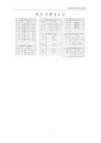
K/iK Series AC Servo Driver 150mm square flange 180mm square flange Standard definition Electromagnetic brake Without rabbet Absolute encoder Magnetic encoder Rotary encoder Incremental standard type 380V servo motor 48V servo motor X7:Production line X6:生产线别 Meaning Code Blank N production line Z
Open the catalog to page 10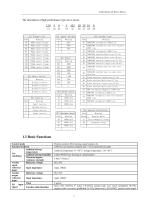
K/iK Series AC Servo Driver The description of high performance type servo motor: TAMAGAWA incremental 2500 line TAMAGAWA incremental save wire harness 2500 line TAMAGAWA incremental 5000 line TAMAGAWA absolute Multi-turn 17 bit TAMAGAWA absolute Multi-turn 20 bit TAMAGAWA absolute Single-turn 17 bit TAMAGAWA absolute Single-turn 20 bit TAMAGAWA winding-type one pair pole resolver TAMAGAWA winding-type two pair pole resolver Nikon absolute Single-turn 17 bit Nikon absolute Multi-turn 17 bit Nikon absolute Single-turn 23 bit Nikon absolute Multi-turn 23 bit AMS incremental Magnetic 1000 line NEMICON...
Open the catalog to page 11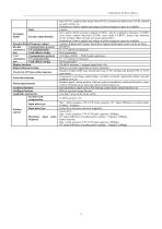
K/iK Series AC Servo Driver Point IO output Signal Function (distributable) Encoder divided frequency output Communication protocol RS-485 communica 1:N communication tion Axial address setting Communication protocol CAN communica 1:N communication tion Axial address setting Display functions Regeneration processing Overtravel (OT) prevention function Protection functions Monitoring functions Auxiliary functions Intelligent function Applicable load inertia Feed-forward compensation Input pulse type Position control Input pulse type Maximum frequency limit (/P-CL), negative-side torque limit (/N-CL),...
Open the catalog to page 12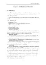
K/iK Series AC Servo Driver Chapter II Installation and Dimension 2.1 Servo Driver K series servo drivers are base-mounted and improper installation may give rise to failures. Please install the servo driver properly by following the instructions below. Storage Condition The servo driver should be kept in a place with an ambient temperature of [-20~+85]℃ when not used. Installation Site ■ Temperature: 0~55°C; ■ Ambient humidity: not higher than 90% RH ( no condensation); ■ Sea level not higher than 1000 m; ■ Maximum vibration: 4.9m/s²; ■ Maximum Impact: 19.6m/s²; ■ Other installation precautions:...
Open the catalog to page 13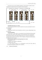
K/iK Series AC Servo Driver If more than one servo driver should be installed in a control cabinet in parallel, the space indicated below should be followed for installation and heat dissipation. Fan ■ Installation direction of servo driver The front (wiring side) of the servo driver should face the operator and should be vertical to the mounting base. ■ Cooling Adequate space should be reserved around the servo driver to ensure cooling through a fan or free convection. ■ Parallel installation As shown above, a space of above 10 mm should be reserved at both sides of the horizontal direction...
Open the catalog to page 14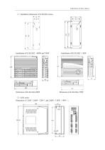
K/iK Series AC Servo Driver
Open the catalog to page 15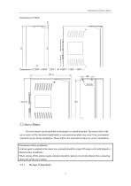
K/iK Series AC Servo Driver 2.2 Servo Motor The servo motor can be installed in horizontal or vertical direction. The service life of the servo motor will be shortened significantly or unexpected accident may occur if any mechanical mismatch occurs during installation. Please follow the instructions below for correct installation. Precautions before installation: Antirust agent is applied at the motor axis end and should be wiped off using a soft cloth dipped in diluent before installation. When wiping off the antirust agent, attention should be paid to prevent the diluent from contacting other...
Open the catalog to page 16
K/iK Series AC Servo Driver The servo motor should be kept in a place with an ambient temperature of [-20~+60]℃ when not used. Servo motor should be installed indoor and the indoor space should meet the following environmental conditions. No corrosive, flammable or explosive air Good ventilation, little dust and dry environment Ambient temperature within 0~40℃ Relative humidity within 26%~80%RH without condensation Easy for maintenance and cleaning Installation Concentricity Flexible coupling should be used as much as possible when connecting to machinery. In addition, axis of servo...
Open the catalog to page 17All SHANGHAI STEP ELECTRIC CORPORATION catalogs and technical brochures
 STEP ROBOT
26 Pages
 K1 series AC Servo Driver
202 Pages


Archived catalogs
 Integrated Controller
2 Pages
 SM.091CA.11
1 Page
 LSA230
1 Page
 EH981
EH9811 Page
 E200 Series
1 Page
 C260 Series
1 Page
 AS620 Elevator Inverter
2 Pages
 EF274/EF980/FSC300
1 Page
 AS320 Elevator Inverter
2 Pages
 Elevator Cable
1 Page


