1. Catalogs
  2. SHANGHAI STEP ELECTRIC CORPORATION
  3. AS450 Series Common Vector Inverter Instruction
video corpo

AS450 Series Common Vector Inverter Instruction

AS450 Series Common Vector Inverter Instruction
1 / 236 PagesView full catalog

AS450 Series Common Vector Inverter Instruction

Product catalog summary
Foreword: The AS450 Series Common Vector Inverter Instruction Manual provides essential guidelines for installation and use, emphasizing the importance of reading the manual thoroughly. Users are encouraged to check for updates on the company's website.
Warranty: The product includes an 18-month warranty from the factory date. Initial fault diagnosis is expected by the user, with STEP offering paid services if needed. Free service is provided for faults due to STEP's responsibility, while paid services apply for faults from improper use or natural disasters.
Chapter 1: Safety Notice This section covers safety signs, usage, transportation, storage, installation, electrical wiring, test runs, maintenance, and disposal. It includes guidelines for motor insulation inspection, thermal protection, and lightning surge protection.
Chapter 2: Product Overview Describes the inverter's nameplate, technical specifications, installation dimensions, and selection of braking units and resistors.
Chapter 3: Installation of the Inverter Details installation steps, mechanical installation requirements, and procedures for installing and disassembling the operator and panel.
Chapter 4: Wiring of the Inverter Provides instructions for connecting the inverter to peripherals, wiring of inverter terminals, main circuit terminal wiring, anti-interference measures, and control circuit terminal wiring.
Chapter 5: Commissioning and Test Run Discusses the run command given, frequency channels, working status, and operation guide for the inverter.
Appendices: Include guides on inverter EMC installation, standard compatibility, and Modbus communication protocol.
LCD Display and Keyboard: Specifications and functionalities of the LCD display and keyboard are outlined, essential for user interaction and control.
Operation: Details procedures for powering on and initializing the system, including display states and control panel functionalities. It covers different operation modes and provides examples of system operation.
Fast Commissioning: Instructions for quick setup of V/F and vector control are provided, enabling efficient system commissioning.
Fault Display: Explains how faults are displayed, aiding in troubleshooting and maintenance.
Functional Parameter Table: An introduction to function code parameters is given, followed by detailed tables categorizing user, control, motor, digital, speed, process, vector, enhanced control, communication, and fault parameters.
Parameter Details: Provides an in-depth look at parameter settings, motor tuning, fault checks, and parameter processing, with a classification and format of parameter groups.
Fault Check: Includes a fault diagnosis flow chart and describes the protection and check functions to ensure system reliability.
Service and Maintenance: Information on warranty, product inquiry, routine, and periodic checks is provided to maintain system performance.
Appendix A - Inverter EMC Installation Guide: Guidelines for noise suppression, wiring requirements, grounding, surge absorber installation, and radiation suppression are detailed to ensure electromagnetic compatibility.
Appendix B - Standard Compatibility: Discusses the standards met by the AS450 series inverter.
Appendix C - Modbus Communication Protocol: Details on command and monitoring data for Modbus communication are provided.
Safety Notice: Provides critical safety information for the AS450 Series Common Vector Inverter, including guidelines on usage, installation, wiring, and maintenance to ensure personal safety and equipment longevity.
Product Overview: The AS450 series is a 400V common vector inverter designed for 3-phase AC asynchronous motors with capacities ranging from 1.1 to 355kW. It is suitable for both simple and advanced motor control applications.
Installation of the Inverter: Details installation steps, mechanical installation requirements, and procedures for installing and disassembling the operator and panel.
Wiring of the Inverter: Provides instructions for connecting the inverter to peripherals, wiring of inverter terminals, main circuit terminal wiring, anti-interference measures, and control circuit terminal wiring.
Technical Specifications: Outlines the technical specifications for the AS450 Series Common Vector Inverter, including output voltage, switch frequency, and rated cable temperature.
Grounding and Wiring: Emphasizes the importance of proper grounding and wiring for motor cables, recommending the use of shielded, armored, or conduit-protected cables.
AC Reactor and Interference Filters: Recommends the use of AC reactors and interference filters to protect the inverter and improve power factor.
Wiring Diagrams and Precautions: Includes detailed wiring diagrams for inverters with and without built-in DC reactors.
Additional Components: Covers output noise filters, AC reactors at the output side, and DC reactors for inverters ≥30kW.
Main Circuit Terminal Label and Function Specification: Outlines the function specifications for main circuit terminals.
Main Circuit Wire Specification: Provides specifications for wire and tightening torque.
Detailed Wiring Description for Terminals of the Main Loop: Provides detailed instructions for wiring the main loop.
Anti-interference Measures: Recommends installing specific noise filters at the inverter output and using surge suppressors for inductive loads.
Control Circuit Terminal Wiring: Provides layout and functional descriptions for control circuit terminals.
Programmable Relay Output: Specifies the programmable relay output function.
Control Circuit Wiring: Details the control circuit wiring specifications.
Digital and Analog Input/Output Terminals: Describes the inverter's digital and analog input terminals.
PG Card Terminals: Describes the wiring for PG card terminals.
Commissioning and Test Run: Highlights safety precautions and outlines the run command channels.
Working Status of the Inverter: Describes the AS450 inverter's main statuses: stop and running.
Run Mode of the Inverter: Supports several run modes: inching run, closed loop run, multi-speed run, and normal run.
Operation Guide: Describes the manipulator's role in operating the inverter.
Operator Functions: Describes the operator's LED indicators, LCD display, and keyboard functions.
Operation Modes: Provides five modes: Parameter Setting, Motor Tuning, Fault Check, Parameter Processing, and Modified Parameters.
Fast Commissioning for V/F and Vector Control: Provides guidelines for fast commissioning in both V/F and vector control modes.
Fault Display: Describes how faults are indicated and provides a table of fault codes and descriptions.
Overview: Provides a technical manual for the AS450 Series Common Vector Inverter, detailing various functional parameters, control optimization settings, communication parameters, fault and display parameters, and product identification parameters.
Protection Parameters: Includes PT and HT protection, bus undervoltage, and no-load torque settings.
Control Optimization Parameters: Includes frequency hopping, inertia compensation, and PWM modulation modes.
Communication Parameters: Includes communication mode options and Modbus parameters.
Fault and Display Parameters: Includes language selection, running record, and troubleshooting parameters.
Product Identification Parameters: Includes inverter specifications and version information.
Parameter Details: Provides instructions for modifying parameters, motor tuning, and fault checks.
Fault Codes and Descriptions: Provides a list of fault codes and descriptions.
Parameter Processing: Describes parameter modification, reset, and protection by passwords.
Classification and Format of Parameter Groups: Organizes parameters into groups based on their function.
User Parameter Groups: Includes basic function parameters like login and modify password settings.
Control Parameter Groups: Includes control mode selection, rotation mode selection, and running command modes.
Start Control Parameters: Describes different start modes available.
Specifications: Provides detailed specifications for the inverter's starting and braking functions.
Starting Procedures: Describes the inverter's ability to identify the motor's rotating speed and execute a direct tracking start.
DC Braking: Explains the DC braking process.
Pre-excitation and Zero Servo Time: Describes pre-excitation time and zero servo time settings.
Tracking Parameters: Details various tracking parameters.
Parking Control: Describes different parking modes.
Braking Function and V/F Control: Covers dynamic braking selection and V/F control parameters.
Motor Parameters: Provides basic motor parameters.
Recommendations: Recommends proper parameter settings for different applications.
Motor Parameters Configuration: Provides detailed instructions on setting motor parameters for an inverter.
Advanced Motor Parameters: Covers advanced settings such as motor tuning modes.
Motor Auxiliary Parameters: Includes rotational inertia and encoder settings.
Motor Protection Parameters: Includes overheat protection and sensor protection threshold settings.
Terminal Parameter Groups: Describes digital input parameters for terminal functions.
Conclusion: Serves as a detailed guide for configuring and optimizing motor parameters in an inverter system.
Specifications and Procedures: Outlines operational parameters and settings for the AS450 Series Common Vector Inverter.
Function Codes and Settings: Provides various function codes for configuring terminal inputs and outputs.
Digital Output Parameters: Details function definitions for digital outputs.
Output Delay and Reset Settings: Allows for setting action and reset delays for output signals.
Frequency and Speed Detection: Uses function codes for frequency consistency and detection.
Critical Information: Emphasizes the importance of setting correct parameters for effective inverter operation.
Specifications and Parameters: Provides detailed specifications for various function codes related to inverter operations.
Analog Input and Output: Outlines the configuration of analog inputs and outputs.
Speed Parameters: Includes basic speed parameters.
Digital Multi-speed Parameters: Details digital multi-speed settings.
Process Control Parameters: Describes process open loop parameters.
Key Recommendations: Emphasizes proper configuration of function codes for optimal inverter performance.
Overview: Provides detailed technical specifications and parameters for the AS450 Series Common Vector Inverter.
PID Control Parameters: Utilizes PID control for process regulation.
Vector Control Parameters: Regulates speed loop parameters.
Enhanced Control Parameters: Defines upper and lower frequency limits.
Key Diagrams: Includes PID functional block diagram and frequency limit schematic.
Conclusion: Provides comprehensive guidance on configuring and optimizing the AS450 Series inverter.
Overview: Provides detailed technical specifications and parameter settings for the AS450 Series Common Vector Inverter.
Key Sections: Includes inverter protection parameters, special function selection, PT and HT signal channels, bus undervoltage and no-load parameters, PWM and frequency settings, V/F optimization and compensation, control system delays, droop control, and power failure management.
Conclusion: Outlines comprehensive settings for optimizing inverter performance.
Parameter Details Overview: Provides detailed specifications and settings for the AS450 Series Common Vector Inverter.
Key Parameter Groups: Includes KEB parameters, communication parameters, display parameters, running record parameters, troubleshooting parameters, and product identification parameters.
Critical Information: Emphasizes default settings, communication settings, regular monitoring, and proper configuration of troubleshooting parameters.
Inverter Product Parameters: Contains fixed parameters of the inverter.
Fault Check: Details inverter faults, codes, reasons, and solutions.
Fault Diagnosis Flow Chart: Provides a procedure for diagnosing faults.
Service and Maintenance Overview: Provides essential guidelines for the service and maintenance of inverters.
Warranty Information: Covers repairs for failures or damages under normal operating conditions.
Product Inquiry: Provides contact information for product issues.
Routine and Periodic Checks: Describes routine and periodic checks.
Appendix A: EMC Installation Guide: Covers noise suppression, wiring requirements, grounding, and surge absorption.
Grounding and Cable Shielding: Emphasizes the importance of connecting the cable shield layer to the grounding cabinet.
Power Cable Filter Guide: Describes power cable filters.
EMC Installation Zones: Outlines the division of EMC installation zones.
Electrical Installation Precautions: Describes precautions for electrical installation.
EMC Standards Compliance: Describes compliance with EMC standards.
Standard Compatibility: Describes compliance with European Low Voltage Directive and EMC regulations.
Modbus Communication Protocol: Details the Modbus communication protocol for the inverter.
Appendix C: Modbus Communication Protocol: Provides detailed information on monitoring data registers and their respective bit functions.
Historical Faults: Records historical faults.
Product Warranty: Describes the warranty period and exclusions.
RoHS Compliance: Outlines compliance with RoHS regulations.
Specifications and Compliance: Outlines compliance with the Electronic Information Products Pollution Control Management Measures and RoHS directive.
Environmental Analysis: Describes the environmental impact of electronic products.
Life Cycle and Disposal: Describes the life cycle and disposal of electronic products.
Recommendations for Disposal: Provides recommendations for the disposal of electronic products.
See more

Catalog excerpts

AS450 Series Common Vector Inverter Instruction-1

AS450 Series Common Vector Inverter Instruction Manual AS450 Series Common Vector Inverter Instruction Manual V1.0 Publication Status: Standard Product Edition: V1.0 All Copyright© reserved by Shanghai Sigriner STEP Electric Co., Ltd. All rights reserved. The information in this document is subject to change without prior notice. No part of this document may in any form or by any means (electronic, mechanical, micro-coping, photocopying, recording or otherwise) be reproduced, stored in a retrial system or transmitted without prior written permission from Shanghai Sigriner STEP Electric Co.,Ltd.

 Open the catalog to page 1
AS450 Series Common Vector Inverter Instruction-2

Shanghai STEP Electric Corporation Foreword Thank you for purchasing AS450 series common vector inverter. To ensure correct installation and use, please carefully read and understand the contents in the instruction prior to use. General Statement During compilation and review, Shanghai Sigriner STEP Electric Co., Ltd (hereinafter referred to as STEP) has checked the consistency between the contents in this document and hardware & software mentioned. But there may be any negligence. We will regularly check the contents covered in this document, and provide the necessary correction in the successive...

 Open the catalog to page 2
AS450 Series Common Vector Inverter Instruction-3

AS450 Series Common Vector Inverter Instruction Manual About Warranty Warranty period Warranty period of the product will be 18 months from the date of leaving factory. Warranty scope Fault diagnosis Principally, the initial fault diagnosis will be executed by the user. But as required by the user, STEP or its service network may provide the paid service. At this time, if the fault is caused by STEP according to the result discussed by both parties, then the service is free. Fault repair If it needs to repair or replace the product according to the fault appeared, STEP may provide free onsite...

 Open the catalog to page 3
AS450 Series Common Vector Inverter Instruction-5

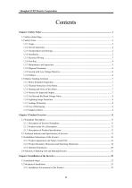
AS450 Series Common Vector Inverter Instruction Manual CHAPTER 1 SAFETY NOTICE CHAPTER 2 PRODUCT OVERVIEW CHAPTER 3 INSTALLATION OF THE INVERTER CHAPTER 4 WIRING OF THE INVERTER CHAPTER 5 COMMISSIONING AND TEST RUN CHAPTER 6 FUNCTIONAL PARAMETER TABLE CHAPTER 7 PARAMETER DETAILS CHAPTER 8 FAULT CHECK CHAPTER 9 SERVICE AND MAINTENANCE APPENDIX A INVERTER EMC INSTALLATION GUIDE APPENDIX B STANDARD COMPATIBILITY APPENDIX C MODBUS COMMUNICATION PROTOCOL

 Open the catalog to page 5
AS450 Series Common Vector Inverter Instruction-6

Shanghai STEP Electric Corporation

 Open the catalog to page 6
AS450 Series Common Vector Inverter Instruction-11

AS450 Series Common Vector Inverter Instruction Manual Chapter 1 Safety Notice This section covers the safety notice and matters needing attention during use of AS450 inverter, safety notice, commissioning/operation, fault overhaul and product disposal treatment etc. relating to safety. To ensure personal safety and lengthen the service life of equipment and its connecting device, please be sure to read the following safety rules and warnings as well as all warning marks attached to the equipment before installation and commissioning. Please carefully read this information. 1.1 Safety-related...

 Open the catalog to page 11
AS450 Series Common Vector Inverter Instruction-12

Shanghai STEP Electric Corporation 1.2 Safety Notes 1.2.1 Usage Safety Notice This series inverter is used to control the operation of three-phase motor at variable speed, other than single-phase motor or other purposes, otherwise inverter fault or fire may be caused. This series inverter can’t be simply applied on the occasions directly related to personal safety, such as medical device. This series inverter is produced under the strict quality management system. If any serious accident or loss may be caused by its fault, safety measures such as redundancy or bypass shall be provided. The product...

 Open the catalog to page 12
AS450 Series Common Vector Inverter Instruction-13

AS450 Series Common Vector Inverter Instruction Manual Be careful of fire or electric shock. corrosive danger. Please hold the product bottom during handling and installation, to avoid crush or break the inverter. Don’t install the equipment in the areas which are easily affected by continuous vibration, shock or electromagnetic interference. The inverter must be installed on the flame retardant object such as metal, and keep away from the flammable material or heat. Be careful of fire! To ensure no foreign matters (sawdust, scrap iron, dust or paper scrap) inside the inverter or on its radiator....

 Open the catalog to page 13
AS450 Series Common Vector Inverter Instruction-14

Shanghai STEP Electric Corporation Turn on the power supply when the run signal is connected, then the motor will run automatically, then please confirm the power supply is connected after the run signal is disconnected. Otherwise personal injury may be caused. Safety Notice For 3-wire system sequential control, wiring can be executed for the control loop after parameters of multifunctional input terminals are set, otherwise personal injury may be caused due to motor rotation. Be sure not to connect the power input cable to motor terminals U/T1, V/T2 and W/T3, nor motor cable to the power supply...

 Open the catalog to page 14
AS450 Series Common Vector Inverter Instruction-15

AS450 Series Common Vector Inverter Instruction Manual function setting is executed). Please prepare the emergency stop switch additionally (stop button is effective only when Please ensure reset alarm after run signal is switched off, otherwise personal injury may be Safety Notice Be sure to have motor no-load commissioning first, and then motor load commissioning. Don’t touch the radiator, motor or other high temperature part when the equipment is running or within a period of time after the equipment is disconnected, to avoid scald. Don’t start or stop the inverter by means of connecting or...

 Open the catalog to page 15
AS450 Series Common Vector Inverter Instruction-16

Shanghai STEP Electric Corporation Don’t touch the circuit board because there is CMOS large scale integrated circuit, to avoid damage to the board. Safety Notice Explosion may be caused when electrolytic capacitor of the main loop and that on the printed board is burning. Poisonous gas may be produced when plastic parts are burning. Disposal of the equipment must be based on the laws and regulations on processing the industrial electronic waste of the related environmental protection department. 1.2.9 Accord with Low Voltage Directive Our products meet the standard of EN61800-5-1:2007, thus...

 Open the catalog to page 16
AS450 Series Common Vector Inverter Instruction-17

AS450 Series Common Vector Inverter Instruction Manual 1.3 Matters Needing Attention 1.3.1 Motor Insulation Inspection The motor shall be executed with insulation inspection when it is used for the first time, reused motor winding. During insulation inspection, be sure to separate the motor wiring from the inverter, 500V megameter is recommended. Insulation resistance measured shall be below 5 MΩ. 1.3.2 Thermal Protection of the Motor If the chosen motor doesn’t match with the rated capacity of AS450 series inverter, especially rated power of the inverter is greater than that of the motor, please...

 Open the catalog to page 17

All SHANGHAI STEP ELECTRIC CORPORATION catalogs and technical brochures

  1. STEP ROBOT

    26  Pages

*Prices are pre-tax. They exclude delivery charges and customs duties and do not include additional charges for installation or activation options. Prices are indicative only and may vary by country, with changes to the cost of raw materials and exchange rates.