
- Catalogs
- SHANGHAI STEP ELECTRIC CORPORATION
- AS180 Series Common Vector Inverter Instruction


AS180 Series Common Vector Inverter Instruction

AS180 Series Common Vector Inverter Instruction
This section emphasizes the importance of adhering to safety protocols when handling the AS180 Series Inverter. Key guidelines include ensuring proper motor insulation, thermal protection, and lightning surge protection. It also advises on cable selection, avoiding high-temperature parts, and using mechanical brake devices with lifting equipment.
The AS180 series inverters are suitable for 3-phase AC asynchronous motors with capacities from 2.2 to 355kW. The overview includes technical specifications, installation dimensions, and braking unit configurations.
The inverter must be installed vertically inside an electrical cabinet with specific space requirements to ensure proper cooling. The manual provides detailed dimensions for various models and emphasizes avoiding environments with dust, corrosive gases, or direct sunlight.
Instructions for connecting the inverter to peripherals and wiring the inverter terminals are provided. It includes diagrams and precautions for main and control circuit terminal wiring, as well as anti-interference measures.
Guidelines for commissioning the inverter include run command channels, operation guides, and fault displays. It also covers fast commissioning for V/F control and provides operation examples.
This section introduces the function code parameters table, detailing user, control, motor, digital, speed, process, vector, enhanced control, communication, and fault parameters.
Details on parameter settings, motor tuning, fault checks, and parameter processing are provided. It explains the classification and format of parameter groups, focusing on user parameter groups.
Maintenance should commence 10 minutes after power off to avoid electric shock. Only appointed staff should perform maintenance, using insulated tools.
Follow environmental regulations for disposal to avoid explosion or toxic gas release.
Products comply with EN61800-5-1:2007 and Low Voltage Directive 2006/95/EC. Ensure grounding and use CE certified components.
Inspect motor insulation to prevent inverter damage. Adjust motor protection parameters if motor and inverter capacities do not match.
Decrease inverter capacity for temperatures above 40℃ and altitudes above 1000m. Use appropriate motor parameters for optimal performance.
Configurations for braking units and resistors are outlined based on inverter capacity and braking time utilization rates.
The modes include Profibus_DP, Modbus, and Canbus, with specific codes assigned to each mode for selection.
Maintenance should commence 10 minutes after power off, ensuring the charge indicator is off and DC bus voltage is below 24 VDC to prevent electric shock. Unauthorized modifications to the inverter are prohibited.
The company offers warranty service for inverters under normal operating conditions within the warranty period.
This section covers noise suppression, wiring requirements, grounding, surge absorption, leakage current solutions, and radiation suppression.
Catalog excerpts

AS180 Series Common Vector Inverter Instruction Manual AS180 Series Common Vector Inverter Instruction Manual V1.0 CHAPTER 1 SAFETY NOTICE Publication Status: Standard Product Edition: V1.0 CHAPTER 2 PRODUCT OVERVIEW CHAPTER 3 INSTALLATION OF THE INVERTER CHAPTER 4 WIRING OF THE INVERTER CHAPTER 5 COMMISSIONING AND TEST RUN CHAPTER 6 FUNCTIONAL PARAMETER TABLE CHAPTER 7 PARAMETER DETAILS CHAPTER 8 FAULT CHECK CHAPTER 9 SERVICE AND MAINTENANCE APPENDIX A INVERTER EMC INSTALLATION GUIDE APPENDIX B STANDARD COMPATIBILITY APPENDIX C MODBUS COMMUNICATION PROTOCOL
Open the catalog to page 1
AS180 Series Common Vector Inverter Instruction Manual
Open the catalog to page 2
AS180 Series Common Vector Inverter Instruction Manual Chapter 1 Safety Notice This section covers the safety notice and matters needing attention during use of and storage, installation, wiring safety notice, commissioning/operation, fault overhaul and product disposal treatment etc. relating to safety. To ensure personal safety and lengthen the service life of equipment and its connecting device, please be sure to read the following safety rules and warnings as well as all warning marks attached to the equipment before installation and commissioning. Please carefully read this information....
Open the catalog to page 7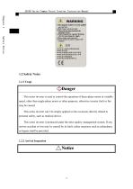
AS180 Series Common Vector Inverter Instruction Manual Chapter 1 Safety Notice 1.2 Safety Notes 1.2.1 Usage This series inverter is used to control the operation of three-phase motor at variable speed, other than single-phase motor or other purposes, otherwise inverter fault or fire may be caused. This series inverter can’t be simply applied on the occasions directly related to personal safety, such as medical device. This series inverter is produced under the strict quality management system. If any serious accident or loss may be caused by its fault, safety measures such as redundancy or bypass...
Open the catalog to page 8
AS180 Series Common Vector Inverter Instruction Manual the information on the order form. If the product is damaged or inconsistent with the The product delivered must be in perfect condition and completely consistent with information on the order form, please contact your local distributor or agent or manufacturer. or put into operation, otherwise it may cause accident. Avoid violent vibration or impact during transportation. If any equipment damage is found, it must be informed to the transport company. Equipment transportation and storage must satisfy the specified ambient conditions. If the...
Open the catalog to page 9
AS180 Series Common Vector Inverter Instruction Manual Please hold the product bottom during handling and installation, to avoid crush or break the inverter. Don’t install the equipment in the areas which are easily affected by continuous Safety Notice vibration, shock or electromagnetic interference. The inverter must be installed on the flame retardant object such as metal, and keep away from the flammable material or heat. Be careful of fire! To ensure no foreign matters (sawdust, scrap iron, dust or paper scrap) inside the inverter or on its radiator. A certain space must be provided between...
Open the catalog to page 10
AS180 Series Common Vector Inverter Instruction Manual Be sure not to connect the power input cable to motor terminals U/T1, V/T2 and Power line and signal line must be laid in different troughs, with minimum space 30cm between them. The cable connected can’t touch any rotating mechanical part. Capacitor or LC/RC noise filter with phase advance isn’t permitted to connect to the output end of the inverter, otherwise internal components of the inverter may be damaged. Wiring cable of the main loop terminal shall be provided with crimp terminals with insulating bush. Selection of input and output...
Open the catalog to page 11
AS180 Series Common Vector Inverter Instruction Manual Be sure to have motor no-load commissioning first, and then motor load commissioning. Don’t touch the radiator, motor or other high temperature part when the Safety Notice equipment is running or within a period of time after the equipment is disconnected, to avoid scald. Don’t start or stop the inverter by means of connecting or disconnecting the power supply repeatedly, otherwise it will damage the equipment/system. Prior to running, please ensure that the motor and machine are within the permissible range of application, otherwise equipment...
Open the catalog to page 12
AS180 Series Common Vector Inverter Instruction Manual to avoid damage to the board. 1.2.8 Disposal Treatment the printed board is burning. Poisonous gas may be produced when plastic parts are burning. Disposal of the equipment must be based on the laws and regulations on processing the industrial electronic waste of the related environmental protection department. 1.2.9 Accord with Low Voltage Directive Our products meet the standard of EN61800-5-1:2007, thus they are in accord with “Low Voltage Directive 2006/95/EC”. Make sure that the whole system meets EC requirement if this inverter is integrated...
Open the catalog to page 13
AS180 Series Common Vector Inverter Instruction Manual 1.3 Matters Needing Attention 1.3.1 Motor Insulation Inspection The motor shall be executed with insulation inspection when it is used for the first Safety Notice time, reused after long time storage or regular inspection, to avoid inverter damage due to insulation failure of motor winding. During insulation inspection, be sure to separate the motor wiring from the inverter, 500V megameter is recommended. Insulation resistance measured shall be below 5 MΩ. 1.3.2 Thermal Protection of the Motor If the chosen motor doesn’t match with the rated...
Open the catalog to page 14
AS180 Series Common Vector Inverter Instruction Manual then it is prohibited to control start or stop of the inverter with this contactor. If the switching elements such as contactor are provided between the output end If a contractor is provided between the power supply and input end of the inverter, and the motor, it shall ensure the inverter to have making-breaking operation without module damage is easily produced. Start and stop of the inverter can be controlled by the terminal. Direct and frequent start and stop with the use of switching elements such as contactor on the input side of the...
Open the catalog to page 15All SHANGHAI STEP ELECTRIC CORPORATION catalogs and technical brochures
 STEP ROBOT
26 Pages
 K/iK series AC Servo Driver
230 Pages
 K1 series AC Servo Driver
202 Pages

Archived catalogs
 Integrated Controller
2 Pages
 SM.091CA.11
1 Page
 LSA230
1 Page
 EH981
EH9811 Page
 E200 Series
1 Page
 C260 Series
1 Page
 AS620 Elevator Inverter
2 Pages
 EF274/EF980/FSC300
1 Page
 AS320 Elevator Inverter
2 Pages
 Elevator Cable
1 Page


