
- Catalogs
- Shanghai Siheng Motor Co., Ltd
- 40AIS83-24-C00330-B1-5-1R

40AIS83-24-C00330-B1-5-1R
1 / 2 PagesView full catalog
40AIS83-24-C00330-B1-5-1R
Product catalog summary
Motor Parameters Overview
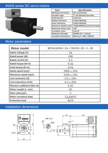
This document details the specifications and wiring information for the 40AIS series DC servo motors.
1. Motor Specifications
- Motor Model: 40AIS series
- Rated Power: Specified in Watts (W)
- Rated Current: Specified in Amperes (A)
- Rated Voltage: Specified in Volts (V)
- Rated Speed: Given in revolutions per minute (rpm)
- Maximum Speed: Maximum allowable rpm
- Moment Coefficient: Torque per Ampere (Nm/A)
- Line Resistance: Resistance of motor winding lines (Ω)
- Line Inductance: Inductance of motor winding lines (mH)
- Motor Length (L): Physical length in millimeters (mm)
- Rotor Pole Pairs: Number of pole pairs in rotor
- Rated Torque: Nominal torque output (N·m)
- Peak Torque: Maximum torque output (N·m)
2. Mechanical and Electrical Characteristics
- Installation Dimensions: Measured from the flange for mounting accuracy
- Winding Connection: Star connection
- Encoder Type: 17-bit Absolute Encoder for precise position feedback
- Shaft Runout: Maximum 0.025 mm to ensure shaft precision
- Radial Clearance: 0.06 mm at 450 g load
- Axial Clearance: 0.08 mm at 450 g load
- Maximum Radial Load: 15 N at 20 mm from bearing center
- Maximum Axial Load: 10 N
- Insulation Class: Class B
- Dielectric Strength: 500 VAC for 1 minute
- Insulation Resistance: Minimum 100 MΩ at 500 VDC
- Motor Insulation Level: Specified for durability and safety
- Protection Level: Not explicitly stated but implied for standard servo motor use
3. Wiring and Electrical Connections
The motor wiring includes multiple terminals with specific functions:
- Input Terminal Common: Used to drive input optocoupler; connected to DC 12-24V (common anode for NPN) or 0V (common cathode for PNP) with current ≥100 mA.
- Input Terminal 01: Function depends on user I/O settings; voltage self-adaptive from DC 5-24V.
- Output Terminals: Include negative and positive ends for instruction direction and command pulses.
- Power Supply Terminals: DC power positive and ground terminals; note that reverse polarity connection will damage the driver.
- Communication Terminals: RS-485 communication positive and negative terminals, communication common, program upgrade clock line, and data cable.
- 3.3V Power Supply: Provided for communication circuits.
4. Critical Notes and Recommendations
- Ensure correct polarity when connecting DC 24V power supply to avoid driver damage.
- Observe rated and maximum speed limits to prevent motor damage.
- Maintain shaft runout and clearance within specified limits for optimal performance and longevity.
- Use the 17-bit absolute encoder for precise position feedback in control applications.
- Follow insulation and dielectric strength specifications to ensure electrical safety.
See more
Catalog excerpts
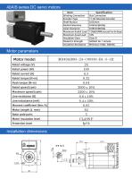
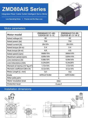
40AIS series DC servo motors Installation dimensions
Open the catalog to page 1All Shanghai Siheng Motor Co., Ltd catalogs and technical brochures
 130mm series 220v
1 Page
 130mm series 380v
1 Page
 130mm series 220v
1 Page
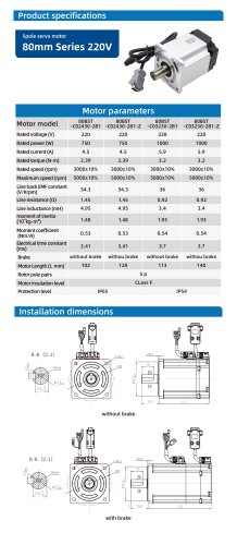 80 mm series 1000w
1 Page
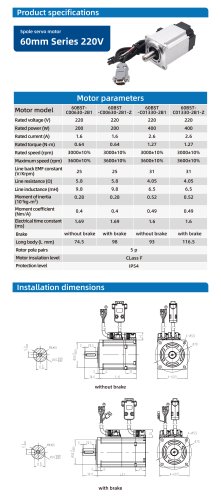 60mm series 220v 400w
1 Page
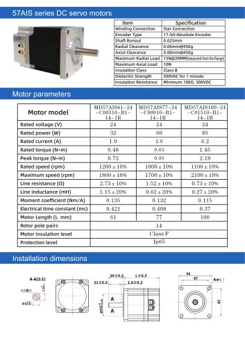 57AIS
57AIS2 Pages
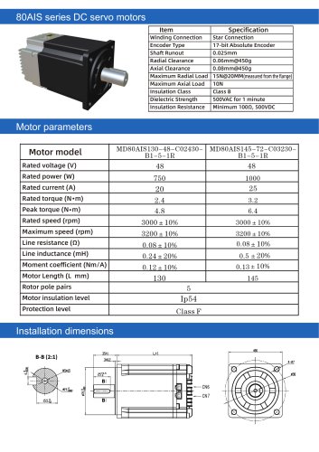 80AIS
80AIS2 Pages
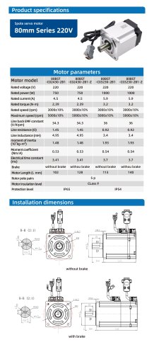 80mm series 750w
1 Page
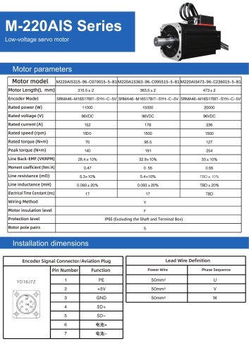 M 220
M 2202 Pages
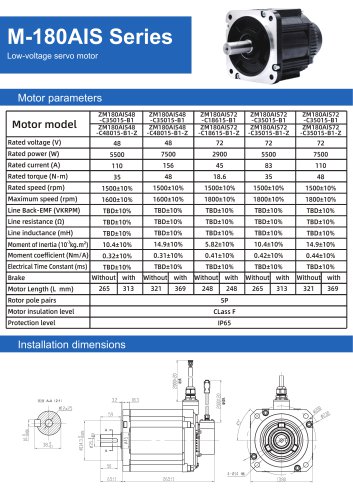 M 180
M 1802 Pages
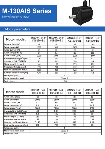 M 130
M 1303 Pages
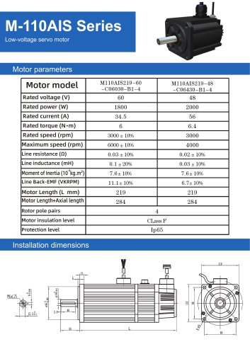 M 110
M 1101 Page
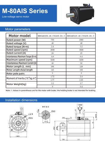 M80
M801 Page
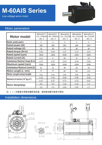 M 60
M 601 Page
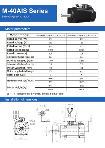 M 40
M 401 Page
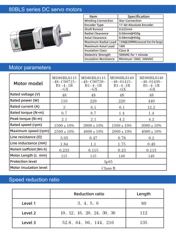 80BLS
80BLS2 Pages
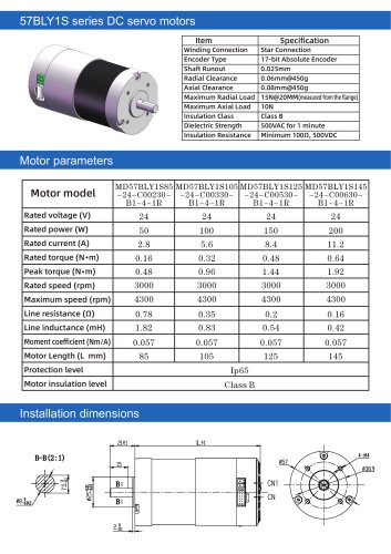 57BLY1S SERIES
2 Pages
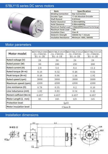 57blys
2 Pages
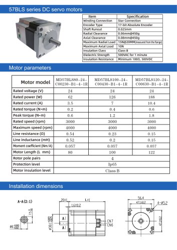 57bls
57bls2 Pages
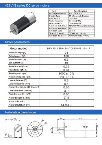 42BLYS
2 Pages
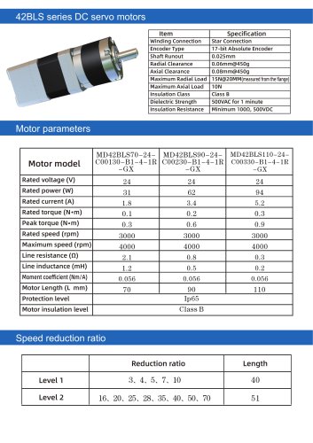 42bls
42bls2 Pages
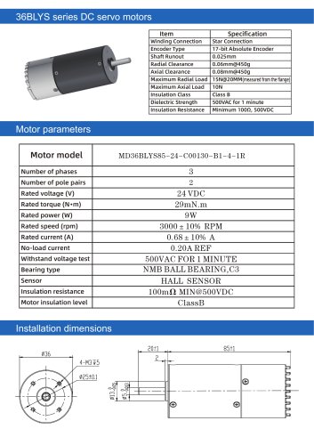 36BLYS
2 Pages
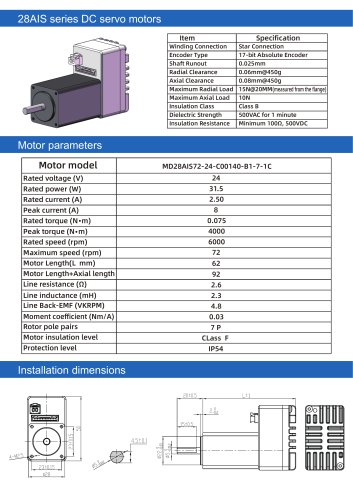 28ais
28ais2 Pages
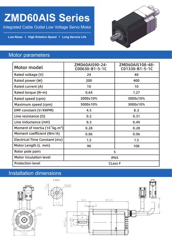 ZMD60AIS series
2 Pages
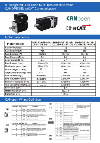 BMD80AIS80-48-C02430-B2-5-1C
3 Pages
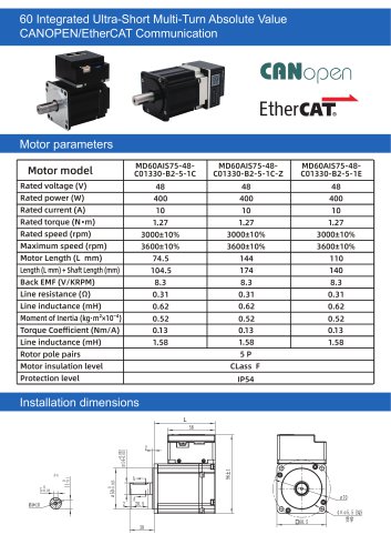 MD60AIS75 series
2 Pages
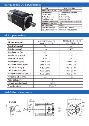 60 AIS series
2 Pages
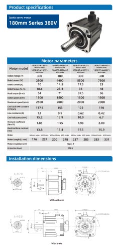 180B series 380v
1 Page
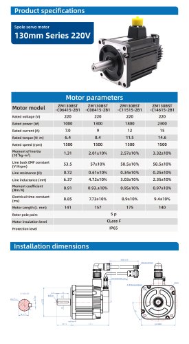 130B series 220v
1 Page
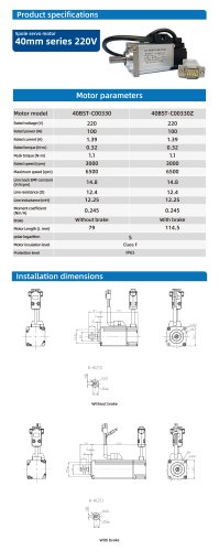 40 series 220v
1 Page
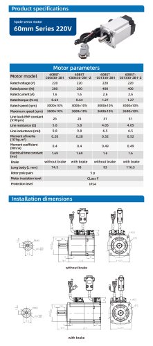 60mm series 220v 200w
1 Page
 Siheng Catolog
43 Pages
Related Searches
- Electromotor
- DC electromotor
- Synchronous motor
- Actuator
- Alternating current motor
- Electric gearmotor
- Linear actuator
- Planetary gearbox
- Electric actuator
- Coaxial gearhead
- EC motor
- Electromotor for industrial applications
- 24 V motor
- Precision gearhead
- Servo-motor
- Right angle gearhead
- Direct current gear-motor
- Compact electromotor
- Hollow-shaft gearhead
- Gear train gear reducer
*Prices are pre-tax. They exclude delivery charges and customs duties and do not include additional charges for installation or activation options. Prices are indicative only and may vary by country, with changes to the cost of raw materials and exchange rates.
About DirectIndustry
DirectIndustry is a marketplace that offers B2B players a complete experience, from product sourcing to purchase. DirectIndustry is an entity of VirtualExpo Group.
Are you a buyer?
Are you a supplier?