Catalog excerpts

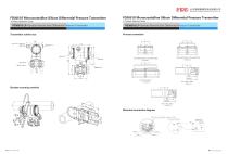
山东福瑞德测控系统有限公司 SHANDONG FRIEND CONTROL SYSTEM CO.,LTD FD3051S Monocrystalline Silicon Differential Pressure Transmitter FD3051S Monocrystalline Silicon Differential Pressure Transmitter ◆ Product Selection Guide ◆ Product Selection Guide FD3051S LF-Sanitary Remote Seal Differential Pressure Transmitter FD3051S LF-Sanitary Remote Seal Differential Pressure Transmitter Technical Parameters Table FD3051S LF-Sanitary Remote Seal Differential Pressure Transmitter Technical Parameters Table Ambient Temperature Supply & Load Requirements -40℃~85℃ -20℃~65℃ (with LCD display, fluorine rubber sealing) Product description FD3051S LF sanitary differential pressure transmitter is used to measure the liquid level, density and pressure of liquid, gas or steam, and then convert it into 4 ~ 20mADC HART current signal output. FD3051S LF can also communicate with FDT375 handheld terminal or FDM100 Modem, and use them for parameter setting and process monitoring. Working condition Storage temperature / transport temperature Digital communication: 230~600Ω Measuring capsule Filling fluid Pressure limit From 3.5kPa absolute pressure to rated pressure Unilateral overload limit Perfor mance and Specifi cation Look the EMC Performance Table Two wire 4~20mADC output with digital communications, linear or square root programmable. HART FSK protocol are superimposed on the 4~20mADC signal. Aluminum with epoxy resin coat Housing Gasket Perbunan(NBR) Name plate and 304 stainless steel tag Electrical connections M20X1.5 cable sealing buckle, the terminal is suitable for 0.5 ~ 2.5mm2 wire DN25/DN40/DN50/DN76.1 Sanitary interface NEPSI Explosion-proof license:Ex dIICT6 NEPSI Intrinsically Safe License:Ex iaIICT4 Allowable temperature:-40℃~65℃ Test items Basic standards Test conditions Performance Level Radiated interference (Housing No Mode (hold): Keep the effective value before the fault. Note: The standard setting of failure alarm is High Mode. Conducted interference(DC power port) Electrostatic Discharge (ESD) Immunity RF electromagnetic field immunity Frequency magnetic field immunity Electrical Fast Transient Burst Immunity Surge Immunity Conducted interference immunity induced by RF field Failure Alarm (the mode can be selected) Function and Specifi cation Response Time The amplifier damping constant is 0.1 sec; the time constant of the sensor and the liquid level flange is 0.2~2s, it depends on the range and range compression ratio. Influence of ambient temperature (no capillary) The additional adjustable time constant is: 0.1 ~ 60s Preheat time Between every 10 ℃ ± 0.08% × Span (when TD = 1) Installation Condition The straight transmitter body can be directly fixed at any position. The best condition is to make the process flange The axis is in a vertical state, and the position deviation will Physical specifica tions Process connection Explosion Protected Type If TD> 10 (TD = maximum range / adjustment range), it is: Perfor mance and Specifi cation Electromagnetic Compatibility(EMC) Power effect As long as: nominal range ≥ minimum range Zero and span can be adjusted to any value within the measurement range in the table DN76.1 2kPa The minimum range shall be the larger value of the minimum range in Table 1 and Table 2. The adjusted range shall not be less than the minimum range. Reference accuracy of range adjustment (Including linearity, hysteresis and repeatability from Zero setting Span Flange and minimum range relationship table 2 and Nominal diameter Minimum range Range DN38/DN40 10kPa DN50/DN51 The low-pressure side is the rated pressure of the transmitter body, and the high-pressure side is the rated force of the remote flange, which may have a correctable zero drift. Technical Parameters Table Transmitter housing Process connection Range of working Density(25℃) temperature Working condition Medium temperature The range is adjusted based on the standard zero point; the stainless steel 316L diaphragm; filling fluid is silicone oil. Power supply Load Standard specification Span and code table 1 Filling fluid Technical Parameters Table The power supply voltage is 24V, the load is 520Ω, the calculation formula is as follows Woring condition produce a correctable zero offset. The case can rotate up to 360° , and the positioning screw can fix it in any position. The capillary component and the remote flange should only Note:(1)Performance level A description: The technical specifications within the limits of normal performance. (2)Performance level B description: Temporary reduction or loss of functionality or performance, it can restore itself. The actual operating conditions, storage, and data will not be changed.
Open the catalog to page 1
山东福瑞德测控系统有限公司 SHANDONG FRIEND CONTROL SYSTEM CO.,LTD FD3051S Monocrystalline Silicon Differential Pressure Transmitter ◆ Product Selection Guide FD3051S LF-Sanitary Remote Seal Differential Pressure Transmitter ◆ Product Selection Guide FD3051S LF-Sanitary Remote Seal Differential Pressure Transmitter Process connection Transmitter outline size FD3051S Monocrystalline Silicon Differential Pressure Transmitter Sealed Joint Terminal Display Bracket mounting method Electrical connection diagram Calibration instrument connection hook Electrical terminal Power SUPP Test Power + Power–
Open the catalog to page 2All Shandong Friend Control System Co. catalogs and technical brochures
-
FDWSS
1 Pages
-
FDWR
1 Pages
-
FDWZ
1 Pages
-
FDWB
1 Pages
-
FD3051LT
1 Pages
-
FD3051LD
1 Pages
-
FD86
1 Pages
-
FD86E/F
1 Pages
-
FD86G
1 Pages
-
FD86T
1 Pages
-
FD80E
1 Pages
-
FD3051ST
1 Pages
-
FD3051S LA/LG
2 Pages
-
FD3051S LD
4 Pages
-
FD3051
1 Pages
-
FD3051S DP
1 Pages
-
FD80B
1 Pages
-
FDWC Temperature Switch
1 Pages


