
- Catalogs
- Sesame Motor Corp.
- SGC series


- Company
- Products
- Catalogs
- News & Trends
- Exhibitions
SGC series

SGC series
Technical Document Summary
This document appears to be a technical specification sheet or catalog page related to mechanical or structural components, possibly connectors or fittings, identified by codes such as SGC and SGE with various model numbers (e.g., SGC-50, SGC-70, SGC-90, SGE-42, SGE-60, SGE-90).
1. Component Identification and Classification
The document lists multiple component codes (C1, C2, C3, etc.), along with other identifiers such as L1 to L11, D1 to D7, and angles (notably 45°). These likely correspond to specific parts, dimensions, or features of the components.
2. Dimensional Data and Parameters
Several numerical values are provided, which appear to represent measurements in millimeters or other units. Examples include lengths (e.g., 44.8, 55.8, 118.1, 145.6), diameters, or heights (B, H). These values are associated with different models (SGC-50, SGC-70, SGC-90, SGE-42, SGE-60, SGE-90), indicating size variations across product lines.
Key parameters include:
- Length ranges (e.g., 20 to 90)
- Dimensional values such as 34.3, 33.5, 60, 44.8, 148.7, 41.5, 28, 90, 55.8, 186.5
- Angles consistently noted at 45°, suggesting standard angular features or cuts
3. Product Series and Variants
The document distinguishes between two main series: SGC and SGE, each with sub-models differentiated by numbers indicating size or capacity (e.g., SGC-50, SGC-70, SGC-90; SGE-42, SGE-60, SGE-90).
Each series has associated dimensional data and possibly different design features, as indicated by the repeated listing of component codes and measurements.
4. Structural or Assembly Features
The repeated references to component codes (C1 to C9), linear dimensions (L1 to L11), and designations such as D1 to D7 suggest a structured approach to defining parts of the components, possibly for assembly or quality control purposes.
The presence of 45° angles multiple times indicates a standard design element, potentially for fitting or joining parts.
5. Summary of Key Data Points
| Model | Key Dimensions (mm) | Angle |
|---|---|---|
| SGC-50 | 44.8, 55.8, 118.1, 145.6 | 45° |
| SGC-70 | 55.8, 186.5, 90 | 45° |
| SGC-90 | Various dimensions up to 186.5 | 45° |
| SGE-42 | 20, 34.3, 33.5, 60, 44.8, 148.7 | 45° |
| SGE-60 | 41.5, 28, 90, 55.8, 186.5 | 45° |
| SGE-90 | Dimensions up to 186.5 | 45° |
6. Observations and Recommendations
- The consistent use of 45° angles suggests a design standard that should be maintained for compatibility and assembly.
- Dimensional variations across models indicate different load capacities or application contexts.
- Component codes and dimension labels should be cross-referenced with detailed drawings or assembly instructions for precise application.
Note: The document appears to be a partial extract or a technical drawing legend with associated dimensional data. For full application, it should be used alongside detailed engineering drawings and specifications.
Catalog excerpts

Specifications Dimensions ★ C1~C9 are motor specific dimensionsfmetric std shown ), Size may vary according to the motor flange chosen. ★ Specification subject to change without notice. SESAME www.sesamemotor.com
Open the catalog to page 3
• SGC Double Stage Dimensions SGCii®£hSiU^'tfl!H ★ C1-C9 are motor specific dimensions(metric std shown ), Size may vary according to the motor flange chosen. ★ Specification subject to change without notice.
Open the catalog to page 4
Products due to human error, natural disasters or other factors lead to poor or damaged, will not be covered under warranty.
Open the catalog to page 5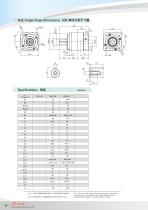
Specifications Unit:mm Dimensions ★ C1-C9 are motor specific dimensions(metric std shown ), Size may vary according to the motor flange chosen. ★ Specification subject to change without notice.
Open the catalog to page 8
Specifications Unifcmm Dimensions ★ C1-C9 are motor specific dimensions(metric std shown ), Size may vary according to the motor flange chosen. ★ Specification subject to change without notice. sesame www.sesamemotor.com
Open the catalog to page 9
Products due to human error, natural disasters or other factors lead to poor or damaged, will not be covered under warranty.
Open the catalog to page 10All Sesame Motor Corp. catalogs and technical brochures
 InLINE (OUTPUT SHAFT) SERIES
86 Pages
 Right Angle Series
35 Pages
 SERVO MOTOR GEARHEAD ENG
162 Pages
 PEC
PEC12 Pages
 PUR series
6 Pages
 PHF series
9 Pages
 CLUTCH BRAKE MOTOR
2 Pages
 ELECTRONIC INSTANT BRAKE
2 Pages
 Magnetic Brake Motor
4 Pages
 TORQUE MOTOR
1 Page
 LINEAR ACTUATOR
1 Page
 GB Series Speed Reducer
2 Pages
 MOTOR AND SPEED REDUCER
70 Pages
 Customization Products
2 Pages
 Precision Gear Motor Catalog
23 Pages
 Motor and Reducer Catalog
30 Pages




Archived catalogs
 PLANETARY GEARHEADS_2016
162 Pages
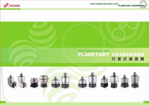 Planetary Gearheads
43 Pages
- Electromotor
- Synchronous motor
- Alternating current motor
- Asynchronous motor
- Planetary gearbox
- Coaxial gearhead
- Precision gearhead
- Right angle gearhead
- Compact gearhead
- Hollow-shaft gearhead
- Gear train gear reducer
- Gearbox for industrial applications
- Transmission gearhead
- Multi-stage gearhead
- Single-stage gearhead
- Shaft gearhead
- Helical gear gearhead
- Machines gearbox
- Dual-stage gearbox
- Low-backlash gearhead