 Website:
SERVOMEX
Group: Spectris
Catalog excerpts

INSTALLATION MANUAL Part Number: Revision: Language:
Open the catalog to page 1
This page intentionally blank
Open the catalog to page 2
WARNING, CAUTIONS AND NOTES This publication includes WARNINGS, CAUTIONS and NOTES which provide, where appropriate, information relating to the following: • WARNINGS: Hazards which will result in personal injury or death. CAUTIONS: Hazards which will result in equipment or property damage. NOTES: Alert the user to pertinent facts and conditions. LETHAL VOLTAGES: THE ELECTRICAL POWER USED IN THIS EQUIPMENT IS AT A VOLTAGE HIGH ENOUGH TO ENDANGER LIFE. BEFORE CARRYING OUT MAINTENANCE OR REPAIR THE EQUIPMENT MUST BE DISCONNECTED FROM THE ELECTRICAL SUPPLY. TESTS MUST BE MADE TO ENSURE THAT...
Open the catalog to page 3
You must install and use the instrument in accordance with the requirements of this manual. If you do not, people may be injured, the protective facilities incorporated into the design of the instrument may not operate as intended, sample gas measurements may not be accurate or the instrument may be damaged. The instrument must be installed by a suitably skilled and competent technician or engineer. You must not modify the instrument in any way (either mechanically or electrically). If you do, the certification of the instrument will be invalidated and it may not operate safely. All...
Open the catalog to page 4
Table of Contents SECTION 1 INTRODUCTION . . . . . . . . . . . . . . . . . . . . . . . . . . . . . . . . . . . . . . . . . 1.1 1.1 Introduction . . . . . . . . . . . . . . . . . . . . . . . . . . . . . . . . . . . . . . . . . . . . . . . . . . . 1.1 1.2 General Description . . . . . . . . . . . . . . . . . . . . . . . . . . . . . . . . . . . . . . . . . . . . . 1.2 1.3 Basic Construction . . . . . . . . . . . . . . . . . . . . . . . . . . . . . . . . . . . . . . . . . . . . . . 1.3 1.4 Options and Accessories . . . . . . . . . . . . . . . . . . . . . . . . . . . . . . . . . . . . . . . . ....
Open the catalog to page 5
SECTION 4 INSTALLATION GAS CONNECTIONS . . . . . . . . . . . . . . . . . . . . . . . 4.1 4.1 Purge Connections (EX1) . . . . . . . . . . . . . . . . . . . . . . . . . . . . . . . . . . . . . . . . 4.1 4.1.1 General Purge Connections . . . . . . . . . . . . . . . . . . . . . . . . . . . . . . 4.1 4.2 End Boss Purge Connection . . . . . . . . . . . . . . . . . . . . . . . . . . . . . . . . . . . . . . 4.3 4.2.1 Introduction . . . . . . . . . . . . . . . . . . . . . . . . . . . . . . . . . . . . . . . . . . . 4.3 4.2.2 End Boss Scrubbers . . . . . . . . . . . . . . . . . . . . . . . . . . . ....
Open the catalog to page 6
SECTION 8 SAFETY APPROVALS . . . . . . . . . . . . . . . . . . . . . . . . . . . . . . . . . . . . 8.1 8.1 EMC and Electrical Safety . . . . . . . . . . . . . . . . . . . . . . . . . . . . . . . . . . . . . . . . 8.1 8.2 Hazardous Area approvals . . . . . . . . . . . . . . . . . . . . . . . . . . . . . . . . . . . . . . . . 8.2 APPENDIX A Modbus Data Mapping . . . . . . . . . . . . . . . . . . . . . . . . . . . . . . . . . . A.1 A.1 Floating Point Numbers . . . . . . . . . . . . . . . . . . . . . . . . . . . . . . . . . . . . . . . . . .A.1 A.2 Measurement Summary . . . . . . . . . . . . ....
Open the catalog to page 7
List of Figures Figure 1.1 Figure 1.2 Figure 2.1 Figure 2.2 Figure 3.1a Figure 3.1b Figure 3.2 Figure 3.3 Figure 3.4 Figure 3.5 Figure 3.6 Figure 4.1 Figure 4.2 Figure 5.1 Figure 5.2 2500 Overall View . . . . . . . . . . . . . . . . . . . . . . . . . . . . . . . . . . . . . . . . 1.2 2500 Construction . . . . . . . . . . . . . . . . . . . . . . . . . . . . . . . . . . . . . . . . 1.4 2500 Positioning Restrictions . . . . . . . . . . . . . . . . . . . . . . . . . . . . . . . . 2.6 2500 Mounting Details . . . . . . . . . . . . . . . . . . . . . . . . . . . . . . . . . . . . . 2.7 2500 AC...
Open the catalog to page 8
This manual contains information regarding installation and hardware configuration of the Servomex 2500 Series analysers (2500GEN/EX1/EX2/DX1/FM2/DM2, 2510GEN/ /EX1/EX2/DX1/FM2/DM2/HTV, 2520GEN/EX2/DX1/FM2/DM2, 2550GEN/EX1/EX2/ DX1/FM2/DM2 variants). GEN – General Purpose/Safe area use. HTV – High Temperature Variant. EX2/DX1 – Certified for International areas that require EPL Gc or Db. EX1 – Certified for International areas that require EPL Gb. FM2/DM2 – Certified for US Class I, II Div. 2 and Zone 2 or Zone 21 areas. Note that the EX1, EX2, FM2 and DM2 versions can also be used where...
Open the catalog to page 9
General Description The Servomex 2500 Series is a single beam, multi wavelength process analyser suitable for monitoring up to three components in a gas sample stream (2550). It is supplied configured to the customer's precise analytical requirements for a stated analysis in a specific background stream. The general layout of the 2500 Series is shown in Figure 1.1. It has been designed for modern industrial environments with the emphasis on rugged construction, reliable performance, simple operation and easy servicing. The analyser is controlled using an on-board microprocessor, which gives...
Open the catalog to page 10
WARNING The EX1 version is intended for use with a suitably certified Purge Control System (PCS). Do not install the EX1 version in a hazardous area without a purge controller. The analyser's software is menu driven and has been designed to be as intuitive as possible, enabling the user to fully operate and control the 2500 with the minimum of familiarisation. NOTE Full technical specifications for 2500 Series Analysers are presented in section 7 of this manual. Basic Construction The basic construction of the 2500 is shown in Figure 1.2. It comprises 2 cast end assemblies (with hinged...
Open the catalog to page 11
The detector end (left side) contains the detector assembly and also the main electronic circuit boards. The display and control panel is also mounted in the hinged lid of this end. 1.4 The 2500 supplied may have been fitted with customer specified options and/or accessories. The full list of available items with brief descriptions is given here. WARNING The surface temperature of heated cells can reach or exceed 100°C The following symbol is used on the heated cell: CAUTION, HOT SURFACE Heated Sample Cell – Electrical Where fitted, this is powered and controlled by the 2500 itself and is...
Open the catalog to page 12All SERVOMEX catalogs and technical brochures
-
Service Guide Issue 4
13 Pages
-
Product Guide Issue 9
15 Pages
-
Gas Guide Issue 5
74 Pages
-
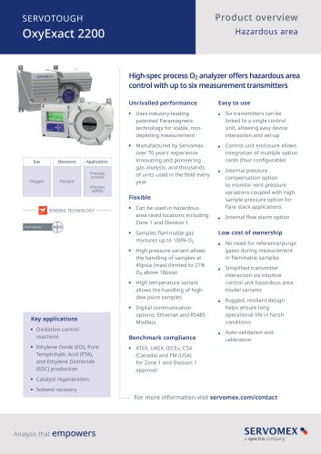
SERVOTOUGH OxyExact 2200
16 Pages
-
SERVOPRO 4900 Multigas
10 Pages
-
SERVOPRO PureGas
4 Pages
-
Servomex Product Portfolio
2 Pages
-
DF560E Operator Manual
144 Pages
-
DF-745 Operator Manual
112 Pages
-
ES 39 Sustainability
11 Pages
-
ES 38 Korea Special
19 Pages
-
ES 37 Clean Air part II
11 Pages
-
ES 36 Purity & Specialty
11 Pages
-
ES 35 Photometric Analysis
11 Pages
-
ES 34 70th Anniversary
15 Pages
-
ES30 Air Separation Units
11 Pages
-
ES 29 Clean Air
11 Pages
-
ES 28 Gas Analysis Applications
11 Pages
-
Sensing Technologies
13 Pages
-
DF760E Operator Manual
182 Pages
-
DF750 Operator Manual
112 Pages
-
DF745SGMax Operator Manual
90 Pages
-
DF-740 Operator Manual
87 Pages
-
DF-730 Operator Manual
82 Pages
-
DF560E Operator Manual 082616
146 Pages
-
DF550E Operator Manual 082616
134 Pages
Archived catalogs
-
SERVOFLEX MiniMP 5200
7 Pages
-
Servomex Gas Guide - Issue 4
76 Pages
-
Servomex Product Guide - Issue 8
15 Pages
-
Servomex Service Guide - Issue 3
13 Pages
-
SERVOTOUGH SpectraScan 2400
2 Pages
-
SERVOTOUGH H2 Scan
2 Pages
-
SERVOPRO NOx
4 Pages
-
SERVOPRO HFID
4 Pages
-
Servomex Service Portfolio
2 Pages
-
Servomex GAS GUIDE issue 3
77 Pages
-
Servomex Service Guide Issue 2
11 Pages
-
Servomex Product Guide Issue 7
13 Pages
-
Servomex Gas Guide 2022
65 Pages


