- Company
- Products
- Catalogs
- News & Trends
- Exhibitions
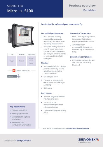
SERVOTOUGH OxyExact 2200 Operator Manual 02210001A_5
1 /98Pages

SERVOTOUGH OxyExact 2200 Operator Manual 02210001A_5
1 /98Pages
Catalog excerpts

OPERATOR MANUAL Part Number: Revision: Language:
Open the catalog to page 1
This page intentionally blank
Open the catalog to page 2
INTRODUCTION. . . . . . . . . . . . . . . . . . . . . . . . . . . . . . . . . . . . . . . . . . . . . . . . 1 1.1 Warnings, Cautions and Notes . . . . . . . . . . . . . . . . . . . . . . . . . . . . . . . . . 1 1.2 Scope of this manual . . . . . . . . . . . . . . . . . . . . . . . . . . . . . . . . . . . . . . . . 1 1.3 Overview of this manual . . . . . . . . . . . . . . . . . . . . . . . . . . . . . . . . . . . . . . 2 Warm-up time . . . . . . . . . . . . . . . . . . . . . . . . . . . . . . . . . . . . . . . . . . . . . . Display contrast adjustment . . . . . . . . . . . . . . . . . . . . ....
Open the catalog to page 3
Flow alarm inputs. . . . . . . . . . . . . . . . . . . . . . . . . . . . . . . . . . Digital inputs . . . . . . . . . . . . . . . . . . . . . . . . . . . . . . . . . . . . . Cross-interference compensation . . . . . . . . . . . . . . . . . . . . . Pressure compensation . . . . . . . . . . . . . . . . . . . . . . . . . . . . . Heater . . . . . . . . . . . . . . . . . . . . . . . . . . . . . . . . . . . . . . . . . . Service and Status. . . . . . . . . . . . . . . . . . . . . . . . . . . . . . . . . CONTROL UNIT CONFIGURATION . . . . . . . . . . . . . . . . . . . . . . . . . . . . . . . 39 7.1...
Open the catalog to page 4
User menu tree. . . . . . . . . . . . . . . . . . . . . . . . . . . . . . . . . . . . . . . . 89 Opererator Xendos 2200 series
Open the catalog to page 5
This page deliberately left blank Opererator Xendos 2200 series
Open the catalog to page 6
List of Figures Figure 1 Figure 2 Figure 3 Figure 4 Figure 5 Figure 6 Figure 7 Figure 8 Figure 9 Figure 10 Control unit display and keypad . . . . . . . . . . . . . . . . . . . . . . . . . . . . 5 Menu screen. . . . . . . . . . . . . . . . . . . . . . . . . . . . . . . . . . . . . . . . . . . 8 Contact Details form. . . . . . . . . . . . . . . . . . . . . . . . . . . . . . . . . . . . . 9 Select Transmitter form . . . . . . . . . . . . . . . . . . . . . . . . . . . . . . . . . 10 Password Entry form . . . . . . . . . . . . . . . . . . . . . . . . . . . . . . . . . . . 15 Measurement format ....
Open the catalog to page 7
This page deliberately left blank Operator Xendos 2200 series
Open the catalog to page 8
Warnings, Cautions and Notes This manual includes WARNINGS, CAUTIONS and NOTES which provide information relating to the following WARNINGS Hazards which could result in personal injury or death. CAUTIONS Hazards which could result in equipment or property damage. NOTES Alert the user to pertinent facts and conditions. 1.2 Scope of this manual This manual covers commissioning and operation of Servomex Xendos 2200 series products. Details of installation, technical specification and spares are held in the relevant installation manual, along with a description of system attributes. Refer to the...
Open the catalog to page 9
Overview of this manual Section 2 provides details related to the commissioning of a system including power-up. Section 3 provides an overview of the appearance and use of the user interface and includes simple examples. This section may be omitted if the user is already familiar with the 2200 user interface. Section 4 provides details of password protection. This section may be omitted if the user has already set up password protection. NOTE The 2200 is supplied with factory configured passwords. These are listed in Section 4. The user may wish to change passwords before placing the system into...
Open the catalog to page 10
It is assumed that the control unit and at least one transmitter unit have been installed in accordance with the requirements of the appropriate installation manual (these are referenced in Section 1.2). 2.1 Warm-up time Electrical power is supplied separately to the transmitter unit and the control unit. Either unit may be switched on first. The control unit will be operational as soon as power is applied. Transmitters must be allowed to warm up for typically one hour. It is recommended that the transmitter and associated sample conditioning system are flushed with a clean, dry, gas (typically...
Open the catalog to page 11
Display contrast adjustment The control unit display contrast may be adjusted if necessary. The adjustment trimpot is accessed through the metal cover on the rear of the hinged door, via a small hole in the side furthest away from the hinge. 2.3 Shutdown procedure Before disconnecting electrical power, the sample conditioning system and transmitter should be flushed with a clean, dry gas. This will reduce the possibility of condensation and subsequent corrosion of the measuring cell. Ensure that all sources of electrical power, including those to relay contacts or other inputs/outputs, are disconnected....
Open the catalog to page 12
The 2200 user interface is a 'menu' driven system, controlled by the keypad. A number of 'forms' then enable the user to view system information and change the configuration of the analyser. This section describes the operation of the keypad and the display, and navigation through the display menus and forms. It is assumed that commissioning has been completed and that, after pressing the MEASURE key (Item 5, below), the control unit display is similar to that shown in Figure 1. Control unit display and keypad Main pane Lower pane Status pane CURSOR keys: up, down, left and right MEASURE key...
Open the catalog to page 13
3.1.1 Display The 2200 display is split into three sections; see Figure 1. Main pane: Under normal operation this shows the measurement and relevant TAG information as shown in Figure 1. On switch-on it may also show other messages as given in Table 1. The pane is also used to display all menus and forms. Lower pane: Under normal operation this pane is clear. It is used to display messages, help text and to facilitate data entry. Scroll indicators will appear in the pane when there are more than four lines of messages. The CURSOR keys may be used to scroll the pane. Status pane: Under normal...
Open the catalog to page 14
NOTE If the unit has been powered up for the first time, the maintenance icon will be visible and the maintenance message 'Date/time not set' will be present in the lower pane. It is not necessary to eliminate entries in either the lower or status panes to proceed with the examples later in this section. 3.1.2 Keypad There are seven keys on the keypad; see Figure 1. The four CURSOR keys are used to scroll displays and select menu and form options. The ENTER key is used to confirm a selection or action and move to the next operation, menu or form as appropriate. It is also used to access the menu...
Open the catalog to page 15All SERVOMEX catalogs and technical brochures
 Gas Guide Issue 6
74 Pages
 Product Guide Issue 10
14 Pages
 Service Guide Issue 5
12 Pages
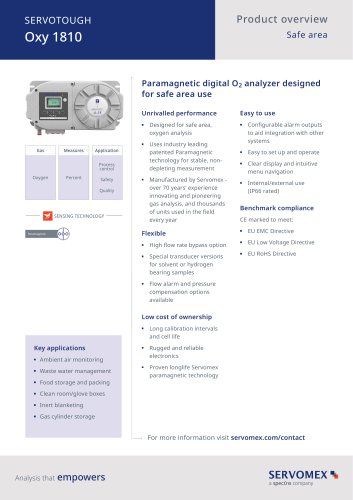 SERVOTOUGH Oxy 1810
9 Pages
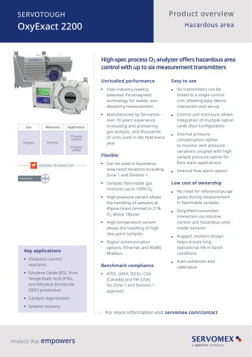 SERVOTOUGH OxyExact 2200
16 Pages
 SERVOPRO 4900 Multigas
10 Pages
 SERVOPRO PureGas
4 Pages
 DF560E Operator Manual
144 Pages
 DF-745 Operator Manual
112 Pages
 ES 39 Sustainability
11 Pages
 ES 38 Korea Special
19 Pages
 ES 37 Clean Air part II
11 Pages
 ES 36 Purity & Specialty
11 Pages
 ES 35 Photometric Analysis
11 Pages
 ES 34 70th Anniversary
15 Pages
 ES30 Air Separation Units
11 Pages
 ES 29 Clean Air
11 Pages
 ES 28 Gas Analysis Applications
11 Pages
 Sensing Technologies
13 Pages
 DF760E Operator Manual
182 Pages
 DF750 Operator Manual
112 Pages
 DF745SGMax Operator Manual
90 Pages
 DF-740 Operator Manual
87 Pages
 DF-730 Operator Manual
82 Pages
 DF560E Operator Manual 082616
146 Pages
 DF550E Operator Manual 082616
134 Pages


Archived catalogs
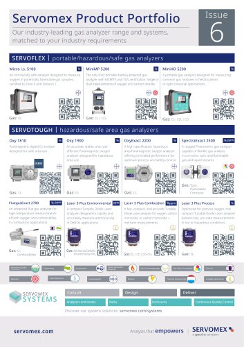
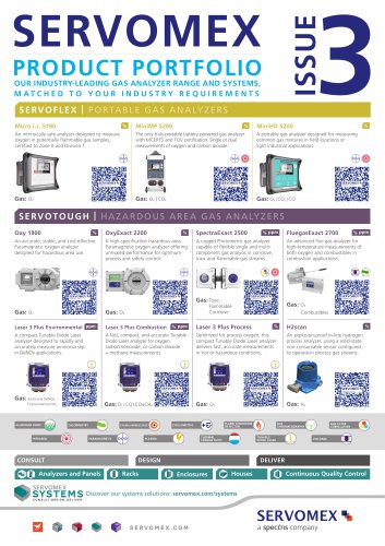
 Servomex Product Portfolio
2 Pages
 SERVOFLEX MiniMP 5200
7 Pages
 Servomex Product Guide - Issue 8
15 Pages
 Servomex Service Guide - Issue 3
13 Pages
 Servomex Gas Guide - Issue 4
76 Pages
 SERVOPRO HFID
4 Pages
 SERVOPRO NOx
4 Pages
 Servomex Product Guide Issue 7
13 Pages
 Servomex Service Guide Issue 2
11 Pages
 Servomex GAS GUIDE issue 3
77 Pages
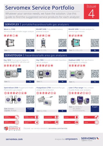
 Servomex Service Portfolio
2 Pages
 SERVOTOUGH H2 Scan
2 Pages
 SERVOTOUGH SpectraScan 2400
2 Pages
 Servomex Gas Guide 2022
65 Pages


- SERVOMEX gas analyzer
- SERVOMEX concentration analyzer
- SERVOMEX monitoring analyzer
- Liquids analyzer
- Automatic analyser
- SERVOMEX benchtop analyzer
- Solids analyser
- SERVOMEX process analyzer
- SERVOMEX portable analyzer
- Continuous analyzer
- Real-time analyzer
- SERVOMEX integration analyzer
- SERVOMEX oxygen analyzer
- Laboratory analyzer
- SERVOMEX digital analyzer
- SERVOMEX compact analyzer
- Infrared analyser
- Calibration analyzer
- Waterproof analyzer
- Temperature analyzer