

- Company
- Products
- Catalogs
- News & Trends
- Exhibitions
SERVOTOUGH Oxy 1900 Operator Manual 01910001B_8

SERVOTOUGH Oxy 1900 Operator Manual 01910001B_8
The safe operation of the SERVOTOUGH Oxy equipment depends on following the installation, operation, and maintenance procedures in the manual. Unauthorized modifications may void warranties, and Servomex disclaims liability for such actions. Health and safety precautions are emphasized throughout.
This section provides an overview of the equipment's construction, including the sample/control and power/signal compartments, and outlines ordering options.
Specifications include general characteristics, environmental limits, electrical data, and gas requirements. Performance metrics and hazardous area certifications are also detailed.
Instructions for safely unpacking the analyser to prevent damage.
Introduces the user interface, including start-up screens, soft key legends, system status icons, and menu options. Covers password protection and editing on-screen data.
Guidelines for mechanical installation, electrical connections, and setting up the analyser, including configuring security levels and automatic validation/calibration.
Describes manual and automatic calibration procedures, including initiating and stopping automatic validation/calibration and viewing calibration history.
Instructions for checking relay signal outputs, pressure compensation, and viewing flow levels. Procedures for switching off the analyser are included.
Outlines maintenance tasks such as cleaning, inspection, and fuse replacement. Discusses preventative maintenance and use with toxic gases.
Information on integrating sample systems and managing corrosive purge gases.
Includes fault definitions, maintenance required statuses, and status annunciations to assist in troubleshooting issues with the equipment.
Details on flow rates, pressure limits, dew points, particulate size, and calibration gas requirements. Performance metrics include oxygen measurement ranges, detection limits, and response times.
Certified for use in Zone 1/Division 1 areas with approvals from ATEX, IECEx, CSA, and CML.
Handle with care, verify electrical supply voltage and sample inlet gas flow rate, and retain shipping documentation.
Comprises display, soft keys, alarm LED, and fault LED. Start-up and measurement screens display system status and measurement data.
Options include viewing measurements, setting up communications, calibrating, and managing alarms with password protection for certain options.
Outlines settings for changing passwords, display language, and calibrating outputs. Includes communication parameters and display settings.
Details on accessing the analyser's serial number and software version for support and diagnostics.
Instructions for editing data on the analyser's screens, including navigating and modifying numerical values.
Emphasizes proper installation by qualified personnel to maintain certification and safety.
Guidelines for mounting the analyser on a rigid vertical surface and avoiding high-velocity dust-laden atmospheres.
Safety instructions for electrical installation, including grounding requirements and the use of suitable fuses and circuit breakers.
Details on connecting auto-validate/calibrate relays and inputs for gas supply validation and calibration routines.
Describes digital communication options and guidelines for proper insulation and connection.
Stresses the importance of adhering to safety standards and proper installation procedures.
Includes procedures for Modbus RS485 and Ethernet connections, mains electrical supply, and sample/calibration gas connections.
Instructions for powering the analyser and initial setup.
Three security levels with varying password protections.
Instructions for adjusting contrast, backlight timer, and setting the clock.
Allows monitoring of measurement drift over time with set tolerance levels.
Settings for pre-warning and inerting, specifying the type of inert gas and its duration.
Outlines a typical automatic calibration sequence, including phases like pre-warning, flushing, inerting, and calibration.
Switch inputs can be configured for remote calibration or automatic validation/calibration.
Settings include target and tolerance values for calibrations and phase settings.
Configurable for different ranges and behaviors during calibration, faults, and under-range conditions.
Instructions for customizing relay coil statuses for various conditions.
Background gases can affect accuracy; corrections are not needed for measurements in nitrogen or air backgrounds.
Outlines error percentages for various background gases and notes that errors can often be ignored.
Procedure for entering compensation if errors cannot be ignored.
Instructions for changing measurement units and entering conversion factors.
Configuration of measurement alarms with settings for alarm levels, hysteresis, and latching options.
Configuration of low and high flow alarms for the Flowcube flow sensor.
Manual calibration is recommended regularly, with specific steps outlined for both low and high calibration gases.
Procedures for initiating, monitoring, and stopping automatic validation/calibration.
Instructions for stopping the process using switch inputs or Modbus commands.
Users can view the 100 most recent validation/calibration points.
Procedures for calibrating the pressure sensor and the Flowcube flow sensor.
Instructions for using specified sample and calibration gases and checking relay signal outputs.
Maintenance should be performed by skilled personnel, with guidelines for cleaning, inspecting for corrosion, and replacing fuses.
Recommends an annual preventative maintenance program.
Maintaining sample gas dew points is crucial to prevent damage to the analyser.
Outlines status definitions and annunciations for faults, maintenance requirements, and service in progress.
Provides a table of symptoms and recommended actions for common issues.
Instructions for storing and disposing of the analyser according to safety and environmental regulations.
Only use specified spares to avoid damaging the analyser and invalidating its certification.
Guidance on implementing Modbus protocol, including setup parameters and supported function codes.
System and transducer data are mapped in blocks of registers, accessible via specific function codes.
System and transducer setup data are available with read-write access for configuration.
Specifies relay states for alarms and range selection.
Managed through a block of coils, writable with function code 05 and readable with function code 01.
Managed through coils, with key functions for calibration mode and auto validation.
Parameters must be configured according to network requirements.
Conversion factors are provided for various unit conversions.
Details correction factors for paramagnetic oxygen measurements.
Lists materials used in the analyser, highlighting their chemical compatibility and corrosion resistance.
The analyser should be submitted for material recovery and recycling according to local regulations.
The analyser complies with several directives and standards, including the Electromagnetic Compatibility Directive and ATEX Directive.
Catalog excerpts
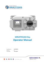
Operator Manual Part Number: Revision: Language: © Servomex Group Limited. 2020
Open the catalog to page 1
This page inten�onally blank.
Open the catalog to page 2
IMPORTANT INFORMATION Con�nued safe and reliable opera�on of this equipment is condi�onal on all installa�on, opera�on and maintenance procedures being carried out in accordance with the appropriate manuals, by personnel having appropriate qualifica�ons, experience and training. Failure to observe the requirements of the manual may result in the user being held responsible for the consequences and may invalidate any warranty. Servomex will accept no liability for unauthorised modifications to Servomex supplied equipment. Servomex has paid particular attention to Health and Safety throughout this...
Open the catalog to page 3
This page inten�onally blank
Open the catalog to page 4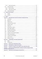
© Servomex Group Limited. 2020
Open the catalog to page 8
© Servomex Group Limited. 2020
Open the catalog to page 11
About this manual Safety information The following icons are used throughout this manual to iden�fy any poten�al hazards that could cause serious injury to people or damage to the equipment: This symbol warns of specific hazards which, if not taken into account, may result in personal injury or death. This symbol warns of specific hazards from laser radia�on. This symbol warns of specific hazards from high temperatures. Other information provided by the manual This symbol highlights where you must take special care to ensure the Analyser or other equipment or property is not damaged. Note: Notes...
Open the catalog to page 12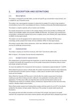
The analyser is designed to provide stable, accurate and specific gas concentra�on measurements, and is suitable for use in hazardous areas. The analyser uses a paramagne�c transducer to determine the oxygen (O2) content of gas samples in concentra�ons of up to 21% in any background mixture, including con�nuously flammable backgrounds. The analyser is simple to operate, with an intui�ve user interface. Gas sample measurements are shown on the analyser display, and are also provided as milliamp (mA) outputs and via Modbus digital communica�on (RS485 and Ethernet). The analyser also provides fault,...
Open the catalog to page 13
protec�on to the measurement transducer. They also form part of the analysers elevated sample pressure (124kPa (18psia)) hazardous area cer�fica�on and the analyser should not be vented to pressures over 110 kPa (16psia) without these fited. They are external to the analyser and simple to change in the case of contamina�on. When sample compartment hea�ng is fited these sintered elements are also heated to 70°C, giving further robustness to moisture droplets or aerosols carried over from the sample system. During normal opera�on, calibra�on and installa�on it is not required to access this side of...
Open the catalog to page 14
Figure 1 - Front of the analyser Key Hinged cover Cer�fica�on label Locking screw * Iden�fica�on/ra�ng label † Threaded cover * The locking screw may be in a different orienta�on with respect to the cover (7), depending on how the cover has been fited. † On the side of the analyser. Contains Servomex contact details, date of manufacture, analyser model and serial number, analyser inlet flow rate, mains voltage ra�ng and op�onal Tag Number.
Open the catalog to page 15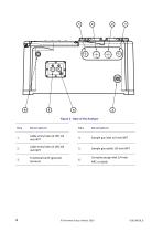
Figure 2 - Base of the Analyser Key Cable entry holes (2 off) 1/2 inch NPT Sample gas inlet 1/4 inch NPT Cable entry holes (2 off) 3/4 inch NPT Sample gas outlet 1/4 inch NPT Func�onal Earth (ground) terminal Corrosive purge inlet 1/4 inch NPT, or blank © Servomex Group Limited. 2020
Open the catalog to page 16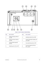
Figure 3 - Base of analyser, Sample Hea�ng Key Cable entry holes (2 off) 1/2 inch NPT Sample gas outlet 1/4 inch NPT Cable entry holes (2 off) 3/4 inch NPT Sample inlet/outlet insula�on and cover plate Func�onal Earth (ground) terminal Cover plate fixing screw, 4 x M4 Sample gas inlet 1/4 inch NPT Corrosive purge inlet 1/4 inch NPT, or blank © Servomex Group Limite
Open the catalog to page 17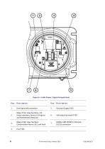
Figure 4 - Inside Power / Signal Compartment Key Earth (ground) connec�on Relays P112, relay func�ons: mA range indica�on, Service in Progress and Maintenance Required Relays P102, relay func�ons: Concentra�on Alarms 1& 2 and Fault Modbus 485 (P109) or Ethernet (U152) connec�on © Servomex Group Limited. 2020
Open the catalog to page 18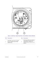
Figure 5 - Inside Power / Signal Compartment - Auto valida�on / Remote Calibra�on Key Relay P803, relay func�ons: Sample gas, low calibra�on gas and high calibra�on gas Switch inputs P804, auto valida�on, autocalibra�on, calibrate low, calibrate high and ini�ate service in progress
Open the catalog to page 19
This page inten�onally blank. © Servomex Group Limited. 2020
Open the catalog to page 20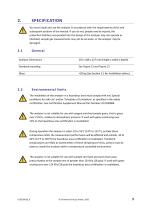
SPECIFICATION You must install and use the analyser in accordance with the requirements of this and subsequent sec�ons of the manual. If you do not, people may be injured, the protec�on facili�es incorporated into the design of the analyser may not operate as intended, sample gas measurements may not be accurate, or the analyser may be damaged. Analyser Dimensions 235 x 448 x 227 mm (height x width x depth) Standard moun�ng >26 kg (See Sec�on 5.1 for Installa�on advice) Environmental limits The installa�on of the analyser in a hazardous area must comply with any ‘Special condi�ons for safe use’...
Open the catalog to page 21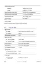
Ambient temperature range Opera�on Opera�ng ambient pressure range Opera�ng ambient humidity range Opera�ng al�tude range Ingress protec�on * Below sea level. † Above sea level. Analyser is suitable for outdoor use within the limits stated above. Electrical data Electrical supply • Maximum power consump�on Internal fuse ra�ng • T 1.0 A H 250 V Electrical supply conductor size Flexible conductors Solid conductors Interface signal relay ra�ngs ‡ Milliamp output • Maximum load resistance Minimum isola�on voltage Output range • Normal sample measurement
Open the catalog to page 22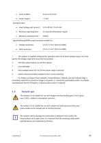
Fault condi�on Under range # Switched Inputs • Input Voltage and Current $ 0.5 seconds (Momentary Inputs) Signal/milliamp/RS485 output terminals suitable for: • Flexible conductors Solid conductors * The analyser is supplied configured for opera�on with one of these voltage ranges. You must specify the voltage range when you order the analyser. ‡ The relay output signals are volt-free signals. User selectable. Only available when the 4 to 20 mA output range is selected. Switch contacts should be suitable for low current switching. ~ For Ini�ate and Stop of Auto valida�on, Autocalibra�on, Calibrate...
Open the catalog to page 23All SERVOMEX catalogs and technical brochures
 Gas Guide Issue 6
74 Pages
 Product Guide Issue 10
14 Pages
 Service Guide Issue 5
12 Pages
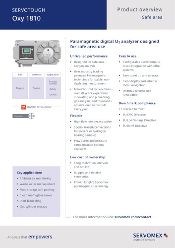 SERVOTOUGH Oxy 1810
9 Pages
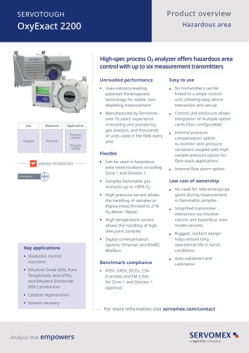 SERVOTOUGH OxyExact 2200
16 Pages
 SERVOPRO 4900 Multigas
10 Pages
 SERVOPRO PureGas
4 Pages
 DF560E Operator Manual
144 Pages
 DF-745 Operator Manual
112 Pages
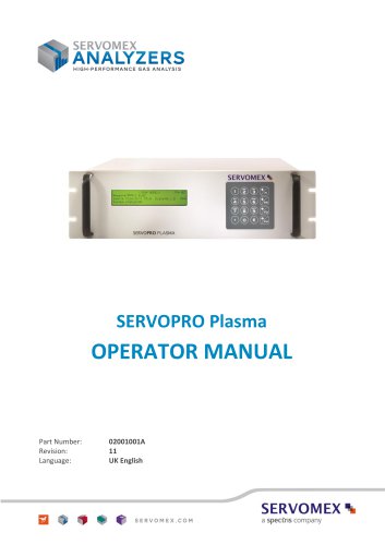 SERVOPRO Plasma Operator Manual
78 Pages
 ES 39 Sustainability
11 Pages
 ES 38 Korea Special
19 Pages
 ES 37 Clean Air part II
11 Pages
 ES 36 Purity & Specialty
11 Pages
 ES 35 Photometric Analysis
11 Pages
 ES 34 70th Anniversary
15 Pages
 ES30 Air Separation Units
11 Pages
 ES 29 Clean Air
11 Pages
 ES 28 Gas Analysis Applications
11 Pages
 Sensing Technologies
13 Pages
 DF760E Operator Manual
182 Pages
 DF750 Operator Manual
112 Pages
 DF745SGMax Operator Manual
90 Pages
 DF-740 Operator Manual
87 Pages
 DF-730 Operator Manual
82 Pages
 DF560E Operator Manual 082616
146 Pages
 DF550E Operator Manual 082616
134 Pages








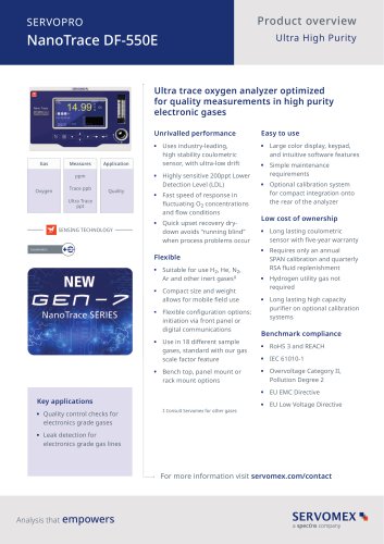


Archived catalogs
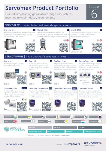
 Servomex Product Portfolio
2 Pages
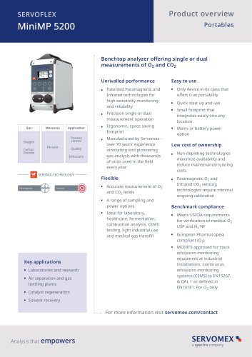 SERVOFLEX MiniMP 5200
7 Pages
 Servomex Product Guide - Issue 8
15 Pages
 Servomex Service Guide - Issue 3
13 Pages
 Servomex Gas Guide - Issue 4
76 Pages
 SERVOPRO HFID
4 Pages
 SERVOPRO NOx
4 Pages
 Servomex Product Guide Issue 7
13 Pages
 Servomex Service Guide Issue 2
11 Pages
 Servomex GAS GUIDE issue 3
77 Pages
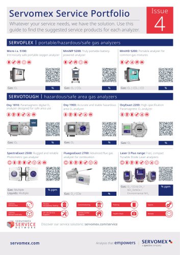
 Servomex Service Portfolio
2 Pages
 SERVOTOUGH H2 Scan
2 Pages
 SERVOTOUGH SpectraScan 2400
2 Pages
 Servomex Gas Guide 2022
65 Pages


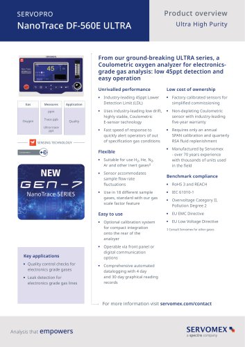


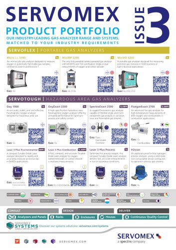
- SERVOMEX gas analyzer
- SERVOMEX concentration analyzer
- SERVOMEX monitoring analyzer
- Liquids analyzer
- Automatic analyser
- SERVOMEX benchtop analyzer
- Solids analyser
- SERVOMEX process analyzer
- SERVOMEX portable analyzer
- Continuous analyzer
- Real-time analyzer
- SERVOMEX integration analyzer
- SERVOMEX oxygen analyzer
- Laboratory analyzer
- SERVOMEX compact analyzer
- SERVOMEX digital analyzer
- Infrared analyser
- Calibration analyzer
- Waterproof analyzer
- Temperature analyzer