

- Company
- Products
- Catalogs
- News & Trends
- Exhibitions
SERVOTOUGH Laser 3 Plus Operator Manual 07931001B_6

SERVOTOUGH Laser 3 Plus Operator Manual 07931001B_6
- The document emphasizes the importance of adhering to safety protocols to prevent injury or equipment damage. Specific symbols indicate hazards such as laser radiation, high temperatures, asphyxiation, and nitrogen gas. Users are advised to read the manual thoroughly before installation or use.
- Markings on the equipment indicate safety and certification information.
- The SERVOTOUGH Laser 3 Plus is described, including its transmitter and receiver units, mounting assembly, and optional power supply. It is designed for continuous in-situ applications across stacks, ducts, and reactors with path lengths of 0.1 to 25 meters.
- Product specifications and materials in contact with the sample are detailed.
- Details on the keypad, indicator LEDs, and navigation of the user interface are provided. Configuration settings and password protection are discussed.
- User settings, mA inputs/outputs, and measurement alarms are configurable. Relay outputs, filtering, and unit selection are also covered.
- Status, measurement, data logging, saturation, and drift information are included.
- Procedures for saving configuration settings, connecting units to the calibration cell, and performing in-situ validation are outlined.
- Installation preparations, process connections, and electrical connections are detailed. Functional earth/ground requirements and purge connections are specified.
- Service functions, routine maintenance, and cleaning procedures are described. User-replaceable spare parts are listed.
- Details on hazardous area approval, EMC, electrical safety, and product disposal are provided.
- Include display unit conversion, Modbus setup, and French translation of warnings.
- The document outlines the specifications for a high-temperature instrument with a maximum operating temperature of 1500°C. It includes various mounting flange options and supports 4 to 20 mA outputs and inputs, with optional configurations.
- Materials in contact with the sample include 316 stainless steel for flanges and insertion tubes, fluorocarbon O-rings, and optional Chemraz 505.
- Procedures for saving and restoring calibration configurations are outlined. Users at the supervisor level can save and restore configurations, which include both instrument calibration and configuration settings.
- To ensure accurate measurements, it is crucial to configure the analyzer with the correct process pressure, temperature, and laser path length.
- The document outlines the configuration of alarms in an analyzer system. It emphasizes the importance of setting alarm levels correctly to avoid permanent alarm conditions.
- The Laser 3 Plus should not be installed in high-velocity dust-laden atmospheres. Ensure the instrument is installed correctly and safely, with the laser beam enclosed during operation.
- Regularly inspect, test, and replace seals to ensure leak-free external connections at full operating pressure.
- Before fitting the transmitter and receiver, ensure no hazardous gases are released. Use adequate eye protection against dust, dirt, and IR radiation.
- Install the instrument according to safety requirements, National Electrical Code, and local regulations.
- Ensure purge gas pressure is above the process pressure to avoid exposure to hazardous gases.
- Regularly test gas connections for leaks and do not use the equipment until faults are corrected.
- Always wear appropriate PPE to minimize risks, especially when the equipment is hot. Turn off power before maintenance to ensure the laser beam is off and prevent exposure to hazardous radiation.
Catalog excerpts

SERVOTOUGH Laser 3 Plus OPERATOR MANUAL Part Number: ENGLISH UK/US
Open the catalog to page 1
This page intentionally blank © Servomex Group Limited. 2020
Open the catalog to page 2
IMPORTANT INFORMATION Continued safe and reliable operation of this equipment is conditional on all installation, operation and maintenance procedures being carried out in accordance with the appropriate manuals, by personnel having appropriate qualifications, experience and training. Failure to observe the requirements of the manual may result in the user being held responsible for the consequences and may invalidate any warranty. Servomex will accept no liability for unauthorized modifications to Servomex supplied equipment. Servomex has paid particular attention to Health and Safety throughout...
Open the catalog to page 3
This page intentionally blank. © Servomex Group Limited. 2020
Open the catalog to page 4
Transmitter user interface © Servomex Group Limited. 2020
Open the catalog to page 5
General analyzer information © Servomex Group Limited. 2020
Open the catalog to page 6
Certification information 11. Appendix Display unit conversion 12. Appendix Modbus setup © Servomex Group Limited. 2020
Open the catalog to page 7
© Servomex Group Limited. 2020
Open the catalog to page 8
© Servomex Group Limited. 2
Open the catalog to page 9
© Servomex Group Limited. 2020
Open the catalog to page 10
© Servomex Group Limited. 2020
Open the catalog to page 11
This page intentionally blank © Servomex Group Limited. 2020
Open the catalog to page 12
About this manual Safety information The following icons are used throughout this manual to identify any potential hazards that could cause serious injury to people or damage to the equipment: This symbol warns of specific hazards which, if not taken into account, may result in personal injury or death. This symbol warns of specific hazards from laser radiation. This symbol warns of specific hazards from high temperatures. This symbol warns of specific hazards from asphyxiation. This symbol warns of specific hazards from nitrogen gas. Other information provided by the manual This symbol highlights...
Open the catalog to page 13
This page intentionally blank © Servomex Group Limited. 2020
Open the catalog to page 14
1. Safety 1.1 General warnings and cautions If the Laser 3 Plus is used in a manner not specified within this manual, the protection provided by the equipment may be impaired. Failure to observe the requirements of the manual may result in the user being held responsible for the consequences and may invalidate any warranty. Before you attempt to install, commission or use the Laser 3 Plus, read this manual carefully. Do not attempt to install, commission, maintain or use the Laser 3 Plus unless you are trained and competent. Ensure that Purge Port 3 of the Transmitter Unit, ‘Enclosure Out’, is...
Open the catalog to page 15
prevent exposure of personnel and the environment to the hazardous gases. The analyzer may fail if it is used with sample streams that contain substances not compatible with those listed in Section 2.8. Make sure that you install the instrument to conform to all relevant safety requirements, National Electrical Code and any local regulations. The installation must be safe for any extremes of operating conditions which may occur in the operating environment of the Laser 3 Plus. Do not install the analyzer on a surface which is subject to high levels of vibration or sudden jolts. Sample measurements...
Open the catalog to page 16
Relay from Analyzer Main Board Relay from Option Board Relay from Option Board Sealed Device Sealed Device Sealed Device EXPLOSION HAZARD - Substitution of components may impair suitability for CL I, Div 2. (North America only). Make sure that the operating environment is within the limits specified in the product data (section 2.6.5). Do not install the Laser 3 Plus in a high-velocity dust-laden atmosphere. Do not open the enclosure if an explosive atmosphere is present. Do not open the enclosure if the Laser 3 Plus is energized. It is a condition of certification that the unit must be installed...
Open the catalog to page 17
1.4 Markings The Laser 3 Plus includes these external markings. Their locations are shown in section 1.4.1. Follow the appropriate safety instructions and be aware of any warnings about potential hazards. Label locations Figure 1-1: Laser 3 Plus transmitter unit rating label location Figure 1-2: Laser 3 Plus receiver unit certification label location © Servomex Group Limited. 2020
Open the catalog to page 18
Figure 1-3: Laser 3 Plus transmitter unit certification label and EMC / function earth label location Figure 1-4: Laser 3 Plus receiver unit laser label location © Servomex Group Limited. 2020
Open the catalog to page 19
Figure 1-5: Laser 3 Plus transmitter unit laser label location Figure 1-6: Laser 3 Plus mount laser label location © Servomex Group Limited. 2020
Open the catalog to page 20
2. Introduction 2.1 Product description The Laser 3 Plus is an advanced gas analyzer. It comprises a transmitter unit (TU) and a receiver unit (RU), with an optional AC to DC power supply, ancillary equipment and sample cell. The laser radiation detected by a photodetector is amplified and transferred to the transmitter unit through a multi-core cable which connects the receiver and transmitter electronics. The same cable transfers the required power from the TU to the RU. Connectors at each end of the cable, and a removable gland plate, allow removal of the TU and RU for calibration or maintenance....
Open the catalog to page 21
11 Figure 2-2: Laser 3 Plus installation: showing thermal spacer and isolation flange options 1 Laser receiver Adjustable mount (2 variants) Fixed mount or adjustable Laser transmitter Thermal spacer (arrangement 1) Process pipe, stack, duct, etc. Thermal spacer (arrangement 2) Isolation flange (arrangement 1) Isolation flange (arrangement 2) Note: Installation may vary depending on specific application and system requirements as items 3 and 6 are selectable options. If item 6 is required, it must be fitted to the TU side. Items 8, 9,10 and 11 are optional, additional gaskets, fasteners and adaptors...
Open the catalog to page 22
Figure 2-3: Transmitter unit: front, rear, side and under-side views 1 Fault LED (Fault status - amber) Purge 3: Purge gas exit Laser power ON indicator (Status ON -green) Functional / EMC earth (ground) Window purge out (standard) Alarm LED (Alarm status - red) Window purge out (option: isolation flange only) Adjustable mount (alternatively options available) Optical window / transmitter aperture Purge 1: Laser diode gas “IN” Cable entry glands: see section 7.4.2 2 x M16 x 1.5 mm (ports 2 and 3) 2 x M20 x 1.5 mm (ports 1 and 4) © Servomex Group Limited. 2
Open the catalog to page 23All SERVOMEX catalogs and technical brochures
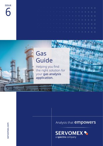 Gas Guide Issue 6
74 Pages
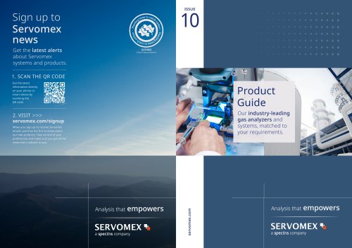 Product Guide Issue 10
14 Pages
 Service Guide Issue 5
12 Pages
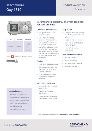 SERVOTOUGH Oxy 1810
9 Pages
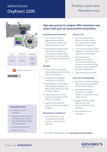 SERVOTOUGH OxyExact 2200
16 Pages
 SERVOPRO 4900 Multigas
10 Pages
 SERVOPRO PureGas
4 Pages
 DF560E Operator Manual
144 Pages
 DF-745 Operator Manual
112 Pages
 SERVOPRO Plasma Operator Manual
78 Pages
 ES 39 Sustainability
11 Pages
 ES 38 Korea Special
19 Pages
 ES 37 Clean Air part II
11 Pages
 ES 36 Purity & Specialty
11 Pages
 ES 35 Photometric Analysis
11 Pages
 ES 34 70th Anniversary
15 Pages
 ES30 Air Separation Units
11 Pages
 ES 29 Clean Air
11 Pages
 ES 28 Gas Analysis Applications
11 Pages
 Sensing Technologies
13 Pages
 DF760E Operator Manual
182 Pages
 DF750 Operator Manual
112 Pages
 DF745SGMax Operator Manual
90 Pages
 DF-740 Operator Manual
87 Pages
 DF-730 Operator Manual
82 Pages
 DF560E Operator Manual 082616
146 Pages
 DF550E Operator Manual 082616
134 Pages











Archived catalogs
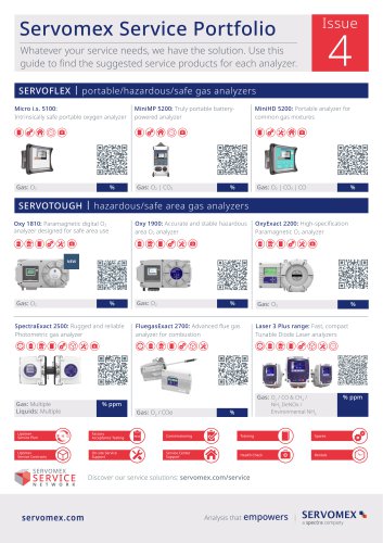
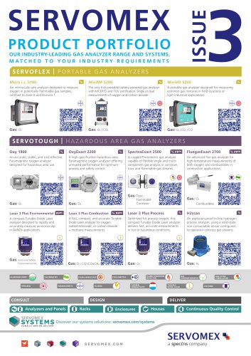
 Servomex Product Portfolio
2 Pages
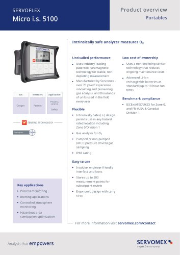
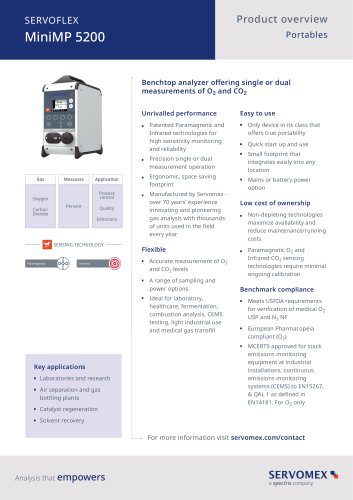 SERVOFLEX MiniMP 5200
7 Pages
 Servomex Product Guide - Issue 8
15 Pages
 Servomex Service Guide - Issue 3
13 Pages
 Servomex Gas Guide - Issue 4
76 Pages
 SERVOPRO HFID
4 Pages
 SERVOPRO NOx
4 Pages
 Servomex Product Guide Issue 7
13 Pages
 Servomex Service Guide Issue 2
11 Pages
 Servomex GAS GUIDE issue 3
77 Pages
 Servomex Service Portfolio
2 Pages
 SERVOTOUGH H2 Scan
2 Pages
 SERVOTOUGH SpectraScan 2400
2 Pages
 Servomex Gas Guide 2022
65 Pages




- SERVOMEX concentration analyzer
- SERVOMEX monitoring analyzer
- Liquids analyzer
- Automatic analyser
- SERVOMEX benchtop analyzer
- Solids analyser
- SERVOMEX process analyzer
- SERVOMEX portable analyzer
- Continuous analyzer
- Real-time analyzer
- SERVOMEX integration analyzer
- SERVOMEX oxygen analyzer
- Laboratory analyzer
- SERVOMEX compact analyzer
- SERVOMEX digital analyzer
- Infrared analyser
- Calibration analyzer
- Waterproof analyzer
- Temperature analyzer