- Company
- Products
- Catalogs
- News & Trends
- Exhibitions
SERVOTOUGH FluegasExact 2700 MiniPurge Installation-Manual for ATEXIECEx
1 /20Pages

SERVOTOUGH FluegasExact 2700 MiniPurge Installation-Manual for ATEXIECEx
1 /20Pages
Catalog excerpts

1. Specification Sheet 2. Application Suitability 3. Description and Principle of Operation 4. Installation of the System 5. Commissioning 6. Maintenance of the System 7. Fault Finding 8. Approval Documents 9. Glossary 10. Drawings and Certificates
Open the catalog to page 1
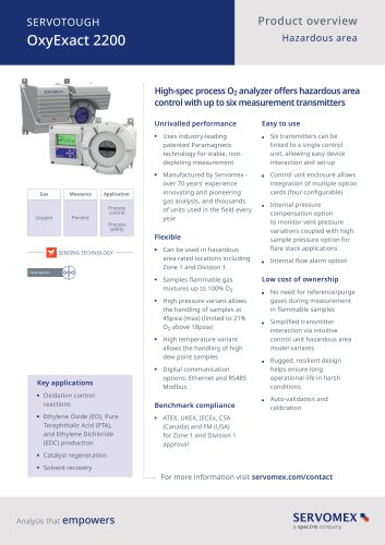
1. Specification Sheet Model No. Purge System Type 07 = MiniPurge Additional Number: Given to System to indicate that Purge System is a special build. Options as Required Approval / Certification = Alarm Only = Manual Override = MIU Mounting Kit = Wall Mounting Bars PA = NI-Ex nA or IS – Ex I circuits ‘Alarms’ : Dry, VFC, SPST N/O contact MiniPurge Housing IEC IEC60079-0, IEC60079-2 IECEx SIR 07.0027X Ex [pzc] IIC T6 Gb Ex [pzc ] IIIC T85ºC Db Tamb -20ºC +55ºC 316L Stainless Steel Neoprene “Top” Mount Gasket Pressurisation Method CF = Continuous Flow Brazil INMETRO - TÜV 12.1462X Ex [pzc] IIC...
Open the catalog to page 3
2. Application Suitability Purge systems may be used for hazards of certain gas groups, refer to Specification Sheet. Apparatus associated with the Purge system, such as intrinsically safe signalling circuits and flameproof enclosures containing switching devices will be limited in their gas group. The certification documentation supplied with any such devices must be checked to ensure their suitability. This system is designed for use primarily with instrument grade compressed air. Where other inert compressed gasses are used (Nitrogen, for example) the user must take suitable precautions so...
Open the catalog to page 4
3. Description and Principle of Operation Circuit diagram ML495 | v16 Expo Technologies UK T: +44 (0) 20 8398 8011 E: [email protected] Expo Technologies US T: +1 (440) 247 5314 E:[email protected] Expo Technologies China T: +86 532 8906 9858 E: [email protected]
Open the catalog to page 5
Continuous flow circuit A continuous flow of protective gas is passed through the pressurized enclosure (in this case, the Servomex Sensor Head). Flow verification occurs on the circuit where the line returns from the sensor head back into the purge system. The flow sensor then measures the differential pressure across a fixed precision orifice. If the differential pressure across the precision orifice is 6.4 mBarg then the flow through the sensor head is approximately 3 Nl/min (-0, +20%) and the purge flow is deemed to be sufficient for purge. If the differential pressure measures below 6.4...
Open the catalog to page 6
4. Installation of the System Connections to Protective Gas supply The system should be connected to a protective gas supply, which is suitable for purging and pressurization. Generally instrument quality compressed air is used, though other inert gas may be usede.g. Nitrogen. It is important that the compressed air / inert gas supply is capable of delivering the quantity required for purging and still maintaining sufficient supply pressure. This means ensuring adequate size of pipe and airline accessories. Over 80% of commissioning problems reported to Expo are due to inadequate sized piping...
Open the catalog to page 7
Note the unit has switching capacity as follows, 3A 250 V 1A 30 Vdc And is suitable to be used on intrinsically safe circuits or on non-incendive circuits that fall within the ratings specified above ML495 | v16 Expo Technologies UK T: +44 (0) 20 8398 8011 E: [email protected] Expo Technologies US T: +1 (440) 247 5314 E:[email protected] Expo Technologies China T: +86 532 8906 9858 E: [email protected]
Open the catalog to page 8
5. Commissioning Before commencing commissioning of the Minipurge®, check that the system has been installed in accordance with this manual. Check that the pressurised enclosure covers are correctly fitted and sealed and that all cable glands and purge pipework connections are tightened. It is recommended to install an external isolation valve with the same, or larger, thread size as the MiniPurge control unit inlet fitting upstream of the connection to aid commissioning and fault finding of the Minipurge® unit. Important – Please note that the internal purge flow switch and high pressure relief...
Open the catalog to page 9
5. Open the flow control valve slowly until the alarm/pressurized indicator just turns from red to green. Clockwise will reduce the flow and anti-clockwise will increase the purge flow. Check that the purge pressure at the test point is 6.4mbarg (+/- 0.2mbarg) at the point that the purge indicator switches from red to green. Check purge indicating contacts switch in relation to the condition to the purge indictor switch. 6. Open the flow control valve further till the purge pressure reaches 19.0mbarg. At or above this point the high pressure relief switch will open to prevent the purge pressure...
Open the catalog to page 10
Normal operation Turn the air supply on or off to start or stop the system. It is the user’s responsibility to ensure power to the equipment is applied after the required purge time has elapsed. Purge Time A specific purge time has been defined for the sensor head pressurised enclosure of 30 minutes. ML495 | v16 Expo Technologies UK T: +44 (0) 20 8398 8011 E: [email protected] Expo Technologies US T: +1 (440) 247 5314 E:[email protected] Expo Technologies China T: +86 532 8906 9858 E: [email protected]
Open the catalog to page 11
6. Maintenance of the System Maintenance of the system The maintenance recommended for the system consists of the following items, supplemented by any additional local requirements imposed by the local Code of Practice. Expo recommends that the commissioning tests be repeated at least every six months. In addition the following checks are also recommended at that time:Check the Spark Arrestors. Remove all debris & corrosion, if replacement is required consult Expo. Check the condition of the air supply filter element. Clean if necessary. At least every two years check the following additional...
Open the catalog to page 12
7. Fault Finding Pressurized/Purging indicator will not turn green during start up Replace pipe work Is the air supply pressure incorrect? Check the air supply pressure at the inlet to the MiniPurge is stable between 4 - 8 Barg / 60 - 115 psi Any significant leakage must be corrected. Check for leaks down the cables or conduit. Ensure leakage does not exceed 3 l/min (0.1cfm) Is the supply pipe to the air inlet as least 6mm OD? Is there excessive leakage from the PE? Is the Pressure / Flow Sensor out of calibration or faulty? Call Expo The basic operation of the Pressure Sensor can be checked...
Open the catalog to page 13All SERVOMEX catalogs and technical brochures
 Gas Guide Issue 6
74 Pages
 Product Guide Issue 10
14 Pages
 Service Guide Issue 5
12 Pages
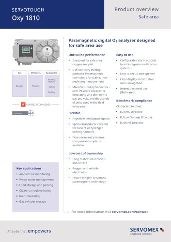 SERVOTOUGH Oxy 1810
9 Pages
 SERVOTOUGH OxyExact 2200
16 Pages
 SERVOPRO 4900 Multigas
10 Pages
 SERVOPRO PureGas
4 Pages
 DF560E Operator Manual
144 Pages
 DF-745 Operator Manual
112 Pages
 ES 39 Sustainability
11 Pages
 ES 38 Korea Special
19 Pages
 ES 37 Clean Air part II
11 Pages
 ES 36 Purity & Specialty
11 Pages
 ES 35 Photometric Analysis
11 Pages
 ES 34 70th Anniversary
15 Pages
 ES30 Air Separation Units
11 Pages
 ES 29 Clean Air
11 Pages
 ES 28 Gas Analysis Applications
11 Pages
 Sensing Technologies
13 Pages
 DF760E Operator Manual
182 Pages
 DF750 Operator Manual
112 Pages
 DF745SGMax Operator Manual
90 Pages
 DF-740 Operator Manual
87 Pages
 DF-730 Operator Manual
82 Pages
 DF560E Operator Manual 082616
146 Pages
 DF550E Operator Manual 082616
134 Pages


Archived catalogs
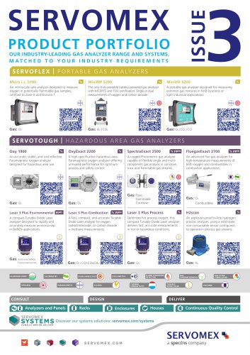
 Servomex Product Portfolio
2 Pages
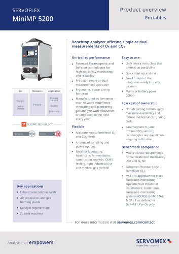 SERVOFLEX MiniMP 5200
7 Pages
 Servomex Product Guide - Issue 8
15 Pages
 Servomex Service Guide - Issue 3
13 Pages
 Servomex Gas Guide - Issue 4
76 Pages
 SERVOPRO HFID
4 Pages
 SERVOPRO NOx
4 Pages
 Servomex Product Guide Issue 7
13 Pages
 Servomex Service Guide Issue 2
11 Pages
 Servomex GAS GUIDE issue 3
77 Pages
 Servomex Service Portfolio
2 Pages
 SERVOTOUGH H2 Scan
2 Pages
 SERVOTOUGH SpectraScan 2400
2 Pages
 Servomex Gas Guide 2022
65 Pages


- SERVOMEX gas analyzer
- SERVOMEX concentration analyzer
- SERVOMEX monitoring analyzer
- Liquids analyzer
- Automatic analyser
- SERVOMEX benchtop analyzer
- Solids analyser
- SERVOMEX process analyzer
- SERVOMEX portable analyzer
- Continuous analyzer
- Real-time analyzer
- SERVOMEX integration analyzer
- Laboratory analyzer
- SERVOMEX oxygen analyzer
- SERVOMEX digital analyzer
- SERVOMEX compact analyzer
- Infrared analyser
- Calibration analyzer
- Waterproof analyzer
- Temperature analyzer