- Company
- Products
- Catalogs
- News & Trends
- Exhibitions
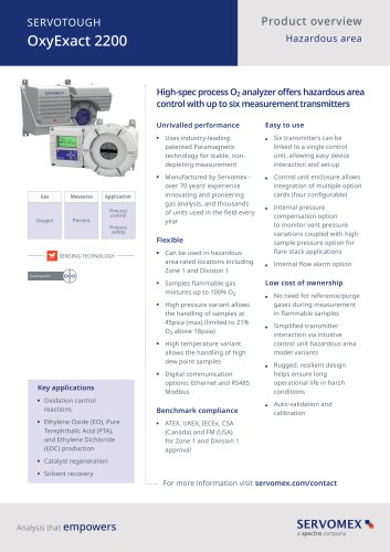
SERVOTOUGH FluegasExact 2700 Installation Manual 02700005D_6
1 /101Pages

SERVOTOUGH FluegasExact 2700 Installation Manual 02700005D_6
1 /101Pages
Catalog excerpts

INSTALLATION MANUAL Part Number: Revision: Language:
Open the catalog to page 1
This page intentionally blank
Open the catalog to page 2
IMPORTANT INFORMATION Continued safe and reliable operation of this equipment is conditional on all installation, operation and maintenance procedures being carried out in accordance with the appropriate manuals, by personnel having appropriate qualifications, experience and training. Failure to observe the requirements of the manual may result in the user being held responsible for the consequences and may invalidate any warranty. Servomex will accept no liability for unauthorised modifications to Servomex supplied equipment. Servomex has paid particular attention to Health and Safety throughout...
Open the catalog to page 3
© Servomex Group Limited. 2016
Open the catalog to page 7
Introduction Warnings, cautions and notes Read this manual and ensure that you fully understand its content before you attempt to install, use or maintain the analyser. Important safety information is highlighted in this manual as WARNINGS and CAUTIONS and NOTES, which are used as follows WARNING Warnings highlight specific hazards which, if not taken into account, may result in personal injury or death. CAUTION Cautions highlight hazards which, if not taken into account, can result in damage to the analyser or to other equipment or property. NOTES Alerts the user to pertinent facts and conditions....
Open the catalog to page 8
General safety information WARNING You must install and use the analyser in accordance with the requirements of this section and subsequent sections of the manual. If you do not, people may be injured, the protection facilities incorporated into the design of the analyser may not operate as intended, sample gas measurements may not be accurate, or the analyser may be damaged. The analyser must be installed by a suitably skilled and competent technician or engineer. You must not modify the analyser in any way (either mechanically or electrically). If you do, the certification of the analyser will...
Open the catalog to page 9
Hazardous Area approval and certification Copies of all hazardous area certificates are provided in the Certificate Manual (part number 02700008D) which is supplied with each hazardous area certified unit. Unpacking WARNING The sensor head and control unit weigh approximately 17Kg (37.5lb) and 11Kg (24.3lb) respectively and care must be taken when handling. Remove the analyser components from their packing and inspect for obvious external damage. If damage has occurred, inform Servomex or its agent immediately. Retain all packing and shipping information for future use. © Servomex Group Limited....
Open the catalog to page 10
Analyser Overview Overview Figure 1 Analyser sensor head and control unit overview 1 Terminal enclosure cover Sample probe Sensor head cover Sample probe filter Control unit Wall mounting brackets Flue/process wall The SERVOTOUGH FluegasExact Combustion Gas Analyser measures the oxygen concentration and/or the level of unburned combustibles. The analyser comprises two separate units which may be mounted up to 300m (975ft) apart for oxygen only and 100m (325ft) apart whenever the combustibles measurement option is fitted. An overall system will consist of sensor head/sample probe/filter mounted...
Open the catalog to page 11
ensure that both the sensor head and control unit have their own separate power supply. Also required is a compressed air supply with a pressure regulator to control the aspirator air supply. Optional utility units are available to supply the sensor head with compressed air, or compressed air and calibration gases. Details of these units can be found in the User and Installation manual for the Utilities Unit, part number 02730001A. An optional sample flow alarm is also available with an external flow alarm relay box. Sensor head description The sensor head is flange mounted on to the flue wall...
Open the catalog to page 12
Installation of Sensor Head and Probe Tube Installation location Refer to Figure 2. NOTE All Servomex adaptor flanges, interface flanges, probe support tubes, stand-offs and thermal spacers, including the integral flange on the sensor head, are suitable for fitting onto the standard flanges (raised face [<1.6mm] or flat faced). They do not comply with any national or international standards and the analyser’s maximum process pressure is limited to 0.34 barg (5 psig). Select a location which allows convenient access for installation and maintenance to the terminal box enclosure. The sensor head...
Open the catalog to page 13
Ambient operating temperature Storage temperature Ingress protection AC power supply Factory set for either a) 100-120Vac 50/60Hz b) 220-240Vac 50/60Hz Overvoltage category Pollution degree The sensor head/terminal box is rated Pollution Degree 2. The sample probe protruding into the flue and the adjacent face of the flange is rated Pollution Degree 4. See Note 1 Relative humidity Note 1: Where the installation is such that the enclosure ingress protection IP66 is maintained and the covers remain securely fitted, the apparatus is suitable for use in locations where there may be significant deposits...
Open the catalog to page 14
WARNINGS When fitted with a sample probe and interconnecting cables the sensor head may weigh over 18 kg with the load being unbalanced. Consequently, the following precautions shall be taken before and during its installation: The sensor head is heated and may be attached to a hot flue and so the appropriate protective equipment shall be worn to minimise the risk of burns. Installers shall be appropriately trained in manual handling. The work shall be planned to minimise any stooping, stretching or reaching above shoulder height or sideways twisting of the body. Floors or platforms shall be...
Open the catalog to page 15
Figure 2. Sensor head dimensions (typical) 1 Purge gas entry 1/4” NPT (INT) or blanking plug Sample vent port 1/8” NPT (INT) Signal cable entry 3/4” NPT (INT) or specified adaptor Sample probe connection 1/2” NPT (INT) Mains cable entry 3/4” NPT (INT) or specified adaptor Calibration gas / blowback gas inlet 1/4” OD compression fitting Aspirator air supply inlet 1/8” NPT (INT) Purge gas exit 1/4” NPT (INT) or breather fitting Analyser mounting flange 4” Unused entry © Servomex Group Limited. 20
Open the catalog to page 16All SERVOMEX catalogs and technical brochures
 Gas Guide Issue 6
74 Pages
 Product Guide Issue 10
14 Pages
 Service Guide Issue 5
12 Pages
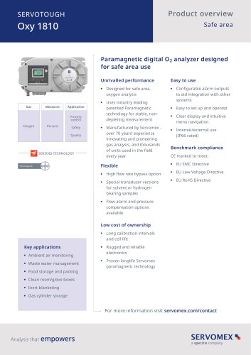 SERVOTOUGH Oxy 1810
9 Pages
 SERVOTOUGH OxyExact 2200
16 Pages
 SERVOPRO 4900 Multigas
10 Pages
 SERVOPRO PureGas
4 Pages
 DF560E Operator Manual
144 Pages
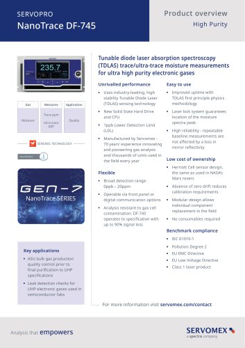
 DF-745 Operator Manual
112 Pages
 ES 39 Sustainability
11 Pages
 ES 38 Korea Special
19 Pages
 ES 37 Clean Air part II
11 Pages
 ES 36 Purity & Specialty
11 Pages
 ES 35 Photometric Analysis
11 Pages
 ES 34 70th Anniversary
15 Pages
 ES30 Air Separation Units
11 Pages
 ES 29 Clean Air
11 Pages
 ES 28 Gas Analysis Applications
11 Pages
 Sensing Technologies
13 Pages
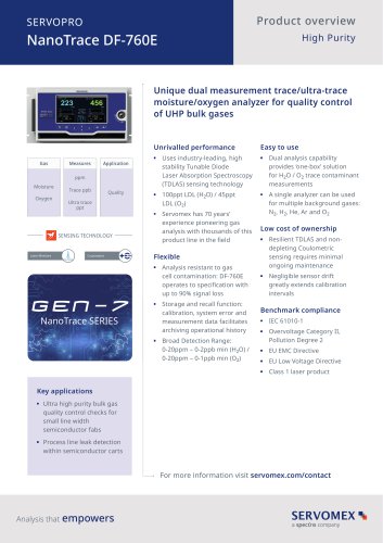
 DF760E Operator Manual
182 Pages
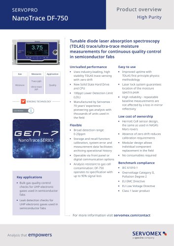
 DF750 Operator Manual
112 Pages
 DF745SGMax Operator Manual
90 Pages
 DF-740 Operator Manual
87 Pages
 DF-730 Operator Manual
82 Pages
 DF560E Operator Manual 082616
146 Pages
 DF550E Operator Manual 082616
134 Pages


Archived catalogs
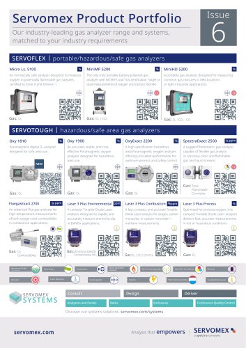
 Servomex Product Portfolio
2 Pages
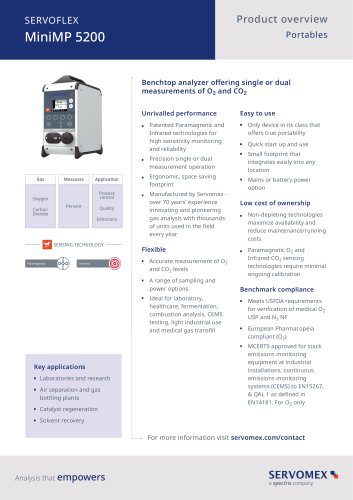 SERVOFLEX MiniMP 5200
7 Pages
 Servomex Product Guide - Issue 8
15 Pages
 Servomex Service Guide - Issue 3
13 Pages
 Servomex Gas Guide - Issue 4
76 Pages
 SERVOPRO HFID
4 Pages
 SERVOPRO NOx
4 Pages
 Servomex Product Guide Issue 7
13 Pages
 Servomex Service Guide Issue 2
11 Pages
 Servomex GAS GUIDE issue 3
77 Pages
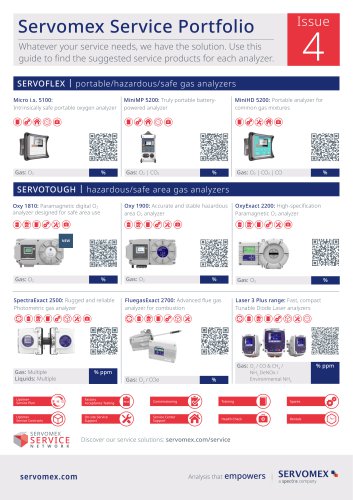
 Servomex Service Portfolio
2 Pages
 SERVOTOUGH H2 Scan
2 Pages
 SERVOTOUGH SpectraScan 2400
2 Pages
 Servomex Gas Guide 2022
65 Pages


- SERVOMEX gas analyzer
- SERVOMEX concentration analyzer
- SERVOMEX monitoring analyzer
- Liquids analyzer
- Automatic analyser
- SERVOMEX benchtop analyzer
- Solids analyser
- SERVOMEX process analyzer
- SERVOMEX portable analyzer
- Continuous analyzer
- Real-time analyzer
- SERVOMEX integration analyzer
- Laboratory analyzer
- SERVOMEX oxygen analyzer
- SERVOMEX digital analyzer
- SERVOMEX compact analyzer
- Infrared analyser
- Calibration analyzer
- Waterproof analyzer
- Temperature analyzer