- Company
- Products
- Catalogs
- News & Trends
- Exhibitions
SERVOTOUGH 1800B Quick Start Guide 01800003B_4
1 /27Pages

SERVOTOUGH 1800B Quick Start Guide 01800003B_4
1 /27Pages
Catalog excerpts

QUICK START MANUAL Part Number: Revision: Language:
Open the catalog to page 1
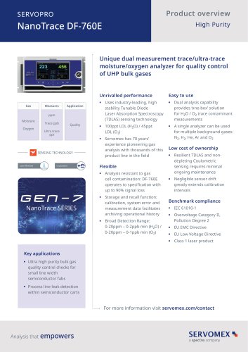
RELAY CONTACTS SHOWN IN DE-ENERGISED POSITION RANGE FLOW ALARM ALARM 2
Open the catalog to page 5
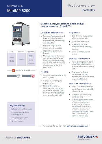
FITTED
Open the catalog to page 6
Warnings, Cautions and Notes This publication includes WARNINGS, CAUTIONS and NOTES which provide information relating to the following: WARNINGS Hazards which could result in personal injury or death. CAUTIONS Hazards which could result in equipment or property damage. NOTES Alert the user to pertinent facts and conditions. 1.2 Scope of this manual This manual covers installation, normal operation and routine maintenance on xendos 1800 Series analysers. For the latest technical specification refer to the Technical Data Sheet. Addresses for technical assistance and spares are given on the...
Open the catalog to page 8
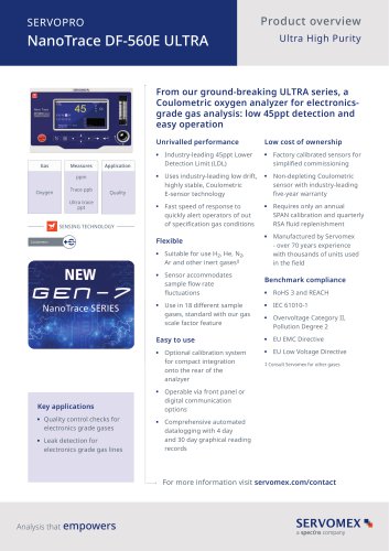
Mounting details 1. M6 bolt (4 off) 5mm allen key 7. Purge outlet (if used) 2. LH cover (hinged) 8. Sample outlet 3. Display window 9. Sample inlet 4. RH cover 10. Cable entries (3 off) 5. M8 mounting slot (4 off) 11. M6 earth stud 6. Purge inlet (if used) 12. Breather Port (Sample, Purge Inlet / Outlet and Breather Port - ¼”NPT.INT) Figure B Electrical connections 1. Range contacts 7. Electrical supply terminals 2. Flow Fail alarm contacts 8. Output cable entry 3. Alarm 2 contacts 9. Supply cable entry 4. Alarm 1 contacts 10. Alarm cable entry 5. Linear non isolated Output signals(Cable entries...
Open the catalog to page 9
Unpacking WARNING The xendos 1800 weighs approximately 26kg (57lbs) and care must be taken when handling. It is recommended that it is lifted with the fingers positioned underneath the rear casting. Remove the xendos 1800 from its packing and inspect it for damage. If damage has occurred, inform Servomex or its agent immediately. Please retain all packing and shipping information for future use. Select a location which allows convenient access for installation and maintenance and will minimise ambient temperature fluctuations and vibration. The analyser must be mounted securely to a rigid vertical...
Open the catalog to page 10
Ambient Operating Conditions: Operating Temperature: Storage Temperature: Atmospheric pressure: Panel Mounting A panel mounting option is available, please consult Servomex for further details. Conditions for Safe Use WARNINGS The xendos 1800 is only suitable for installation in a safe non-hazardous area. If the application requires the oxygen analyser to be installed in a hazardous area, then a xendos 1900 Series analyser must be used. The xendos 1800 is not suitable for use with flammable sample gases. If your sample is flammable, then a xendos 1900 Series analyser must be used. Personal...
Open the catalog to page 11
Electrical installation WARNINGS The installer must be satisfied that the xendos 1800 installation conforms to the relevant safety requirements, National Electrical Code and any other local regulations, and that the installation is safe for any extremes of conditions which may be experienced in the operating environment of the analyser. This appliance must be connected to a protective earth. The electrical installation must include a means of isolating electrical power by a switch or circuit breaker external to the analyser and within easy reach of the operator. It must be marked as the disconnecting...
Open the catalog to page 12
Do not exceed the maximum current output load impedance of 600 Ohms. Electrical power should be supplied at 100V to 240Vac ± 10% - 50/60Hz. (Note: The optional internal sample pumps are AC voltage dependant. Ensure that the correct AC input voltage is connected to analysers fitted with a sample pump. A power on LED is illuminated when power is present at the analyser). For compliance with the EMC standards, the external earth / ground connection must always be connected to a local earth / ground. Refer to Figure (A). In addition, the connections to TB2, TB3 and TB4 must always be made using a...
Open the catalog to page 13
Power Connection Electrical Power, 100V to 240Vac ±10%, 50 / 60 Hz, 50VA maximum Terminal Protective Earth Neutral Live Alarm Connection Closes on Alarm 1 or Power Fail Opens on Alarm 1 or Power Fail Common Closes on Alarm 2 or Power Fail Opens on Alarm 2 or Power Fail Common Closes on Flow Fail Alarm or Power Fail Opens on Flow Fail Alarm or Power Fail Common Range Selected Output Connection Range 2 selected 250Vac, 3A 28Vdc, 1A Closes on Range 2 or Power Fail Opens on Range 2 or Power Fail Common Linear Analogue Output Signal Connection 0 to 1 Vdc Oxygen output signal, (non isolated), output...
Open the catalog to page 14
Sample and calibration gas connections CAUTION The sample gas must not be admitted to the analyser until a period of 4 hours has been allowed for warm up, this will prevent condensation of the sample in the measuring cell. The inlet pressure and flow rate for the sample or calibration gas must not exceed the limits specified in the following table or damage could occur. If necessary, an external pressure reducing device must be used to reduce the pressure to the stated limits. When pressurising the sample system for the purpose of leak testing ensure that pressure is increased and decreased...
Open the catalog to page 15
If the automatic flow control device option is fitted no external flow control is necessary, the sample pressure must be between the limits specified in the previous table and/or the latest Technical Data Sheet. If the optional automatic flow control device option is not fitted it will be necessary to regulate the sample pressure / flow within the limits specified in the previous table to ensure stable operation and to prevent damage to the measuring cell. If an external sample pump is used it may be necessary to reduce pressure pulsing with a reservoir. The sample exhaust from the analyser should...
Open the catalog to page 16
the analyser sample pipework with dry nitrogen or good quality instrument air for 10 minutes. The analyser is supplied with a digital display which is always ranged 0 - 100% Oxygen, an isolated current and non-isolated voltage outputs. These outputs may be used simultaneously. The push button Range switch on the front panel and/or the settings of Link 3/4 selects the full scale range of both outputs. The default analyser configuration is as follows: Link Parameter Setting Link LK 1 Alarm 1 Low = 0.0% O2 LK 4 LK 2 Alarm 2 High = 21.0% O2 LK 5 LK 3 Range 1 Parameter Range 2 Flow Alarm Setting 0...
Open the catalog to page 17All SERVOMEX catalogs and technical brochures
 Gas Guide Issue 6
74 Pages
 Product Guide Issue 10
14 Pages
 Service Guide Issue 5
12 Pages
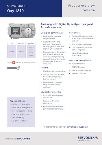 SERVOTOUGH Oxy 1810
9 Pages
 SERVOTOUGH OxyExact 2200
16 Pages
 SERVOPRO 4900 Multigas
10 Pages
 SERVOPRO PureGas
4 Pages
 DF560E Operator Manual
144 Pages
 DF-745 Operator Manual
112 Pages
 ES 39 Sustainability
11 Pages
 ES 38 Korea Special
19 Pages
 ES 37 Clean Air part II
11 Pages
 ES 36 Purity & Specialty
11 Pages
 ES 35 Photometric Analysis
11 Pages
 ES 34 70th Anniversary
15 Pages
 ES30 Air Separation Units
11 Pages
 ES 29 Clean Air
11 Pages
 ES 28 Gas Analysis Applications
11 Pages
 Sensing Technologies
13 Pages
 DF760E Operator Manual
182 Pages
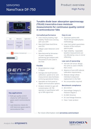
 DF750 Operator Manual
112 Pages
 DF745SGMax Operator Manual
90 Pages
 DF-740 Operator Manual
87 Pages
 DF-730 Operator Manual
82 Pages
 DF560E Operator Manual 082616
146 Pages
 DF550E Operator Manual 082616
134 Pages


Archived catalogs
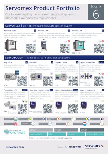
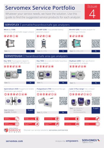
 Servomex Product Portfolio
2 Pages
 SERVOFLEX MiniMP 5200
7 Pages
 Servomex Product Guide - Issue 8
15 Pages
 Servomex Service Guide - Issue 3
13 Pages
 Servomex Gas Guide - Issue 4
76 Pages
 SERVOPRO HFID
4 Pages
 SERVOPRO NOx
4 Pages
 Servomex Product Guide Issue 7
13 Pages
 Servomex Service Guide Issue 2
11 Pages
 Servomex GAS GUIDE issue 3
77 Pages
 Servomex Service Portfolio
2 Pages
 SERVOTOUGH H2 Scan
2 Pages
 SERVOTOUGH SpectraScan 2400
2 Pages
 Servomex Gas Guide 2022
65 Pages


- SERVOMEX gas analyzer
- SERVOMEX concentration analyzer
- SERVOMEX monitoring analyzer
- Liquids analyzer
- Automatic analyser
- SERVOMEX benchtop analyzer
- Solids analyser
- SERVOMEX process analyzer
- SERVOMEX portable analyzer
- Continuous analyzer
- Real-time analyzer
- SERVOMEX integration analyzer
- SERVOMEX oxygen analyzer
- Laboratory analyzer
- SERVOMEX digital analyzer
- SERVOMEX compact analyzer
- Infrared analyser
- Calibration analyzer
- Waterproof analyzer
- Temperature analyzer