

- Company
- Products
- Catalogs
- News & Trends
- Exhibitions
SERVOPRO Plasma Operator Manual
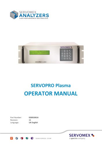
SERVOPRO Plasma Operator Manual
- Scope: The manual provides guidance on the installation, operation, and maintenance of the SERVOPRO Plasma Trace N2 Analyzer.
- Safety Information: It includes essential safety guidelines, highlighting warnings and cautions to prevent personal injury or equipment damage.
- Description: The analyzer is designed for industrial gas analysis, specifically for trace nitrogen in argon or helium, and is not intended for medical use.
- General: The analyzer measures 133 mm x 483 mm x 457 mm and weighs 15 kg.
- Environmental Limits: Suitable for indoor use within 5 to 40°C, with storage limits of -20 to 60°C.
- Electrical Data: Operates on 100-120 Vac / 230-240 Vac, 50-60 Hz, with a maximum power consumption of 45W.
- Sample Gases: Analyzes clean, non-corrosive gases at a flow rate of 25 to 150 ml/min.
- Calibration Gas: Uses high calibration set points of at least 90% FSD N2 in Ar or He.
- Performance: Features a Plasma Emission Detector with ranges from 0-1 to 0-100 ppm and accuracy between ±1% to ±5%.
- Mechanical Installation: Requires additional support under the base and should avoid areas with high vibration or electromagnetic fields.
- Electrical Installation: Must comply with local electrical safety standards and use the provided power supply cord.
- Gas Pipeline Connection: Connections must be leak-free and compatible, with the vent connection at atmospheric pressure.
- Power On and Start-Up: Ensure gas lines are purged with argon before powering on.
- Configuration: Allows setting parameters like auto-ranging and sample flow.
- Calibration: Involves entering zero and span gas values, with automatic range selection based on span value.
- Diagnosis: Provides error and alarm history, and diagnostic tools for system verification.
- Includes cleaning and fuse inspection/replacement procedures, to be performed by qualified personnel.
- Only specified spare parts should be used to avoid damage and warranty voidance.
- Store in a clean, dry area and dispose of according to local regulations and the WEEE Directive.
- The analyzer complies with directives like the Electromagnetic Compatibility Directive and the Low Voltage Directive.
- For support, contact Servomex Group Limited or visit their website for global contact details.
- Automatic Calibration Option: Describes manual or automatic calibration using solenoid valves.
- Trace Nitrogen in Helium Version: Provides specific instructions for helium version, emphasizing stable flow and pressure.
- Dual Background Analyzers: Configuration details for Argon or Helium backgrounds.
- Interface for External Valve Box: Instructions for interfacing with external valve boxes.
Catalog excerpts
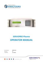
SERVOPRO Plasma Part Number: SERVOMEX \ a spectris company
Open the catalog to page 1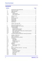
Section Page
Open the catalog to page 2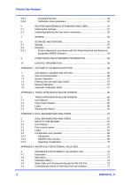
8.2.1 Product disposal in accordance with the Waste Electrical and Electronic
Open the catalog to page 3
Scope of this manual This manual provides installation, operation and routine maintenance instructions for the SERVOPRO Plasma Trace N2 Analyzer, abbreviated to "analyzer" in the remainder of this manual. Safety information Read this manual and ensure that you fully understand its content before you attempt to install, use or maintain the analyzer. Important safety information is highlighted in this manual as WARNINGs and CAUTIONs, which are used as follows: WARNING Warnings highlight specific hazards which, if not taken into account, may result in personal injury or death. Where the above symbol...
Open the catalog to page 6
Description WARNING This analyzer is not a medical device as defined in the medical devices directive 93/42/EEC and is not intended to be used on human beings for the diagnosis, prevention, monitoring, treatment or alleviation of disease, injury or replacement or modification of the anatomy. WARNING The analyzer must not be used as personal protective equipment. The analyzer is designed to meet the needs of the control and product quality applications of industrial gas producers and users, who require fast, accurate and reliable gas analysis. Gas sample measurements are shown on the analyzer...
Open the catalog to page 7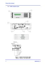
-YJVYEE 'ILET [SERVICE PORT]
Open the catalog to page 8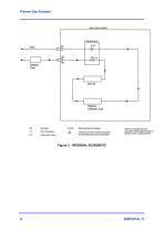
ANALYSER CABINET FLOW MODULE Emission Cell ‘Use only supplied trap wrth Flow Transducer There is a 2 micron frit mounted inside instrument. Other types of traps will Flow control valve the bulkhead acting as a partcle fitter interfere with N j measurements Figure 3 - INTERNAL SCHEMATIC 02001001A 11
Open the catalog to page 9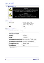
2 SPECIFICATION WARNING The protection, accuracy, operation and condition of the equipment may be impaired if the analyzer is not installed in accordance with the requirements of this and subsequent sections of the manual. WARNING Not suitable for flammable samples. Never pressurise the analyzer. Always remove vent plug before connecting the sample inlet. General Dimensions (Height x Width x Depth): 133 mm x 483 mm x 457 mm (5.25 ins x 19 ins x 18 ins) Environmental limits Equipment is suitable for indoor use only Ambient temperature range Operation: Operating ambient pressure range: 101.3 kPa...
Open the catalog to page 10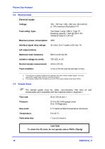
Electrical data Electrical supply Voltage: Fuse rating / type: Two fuses 1 amp / 250 V, Type “F”, Breaking capacity 1.5kA @ 250 V AC miniature fuses 5 x 20 mm Maximum power consumption: Interface signal relay ratings: mA output (active) Maximum load resistance: Isolation voltage (to earth): Normal sample measurement: Fault condition: The analyzer is supplied configured for operation with one of these voltage ranges. You must specify the voltage range when you order the analyzer. The analyser reading may fluctuate by up to 6% if the supply voltage drops below 95Vac Sample Gases The sample gases...
Open the catalog to page 11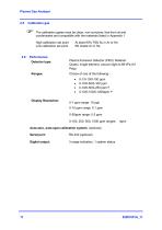
2.5 Calibration gas The calibration gases must be clean, non-corrosive, free from oil and condensates and compatible with the materials listed in Appendix 1 High calibration set point At least 90% FSD N2 in Ar or He Low calibration set point 6N Grade Ar or He 2.6 Performance Detector type: Ranges: Plasma Emission Detector (PED). Material: Quartz, single element, vacuum tight to 69 kPa (10 Psig) Display Resolution: Auto-zero, auto-span calibration system: (optional) Serial port: Digital output: 3 range indication, 1 system status
Open the catalog to page 12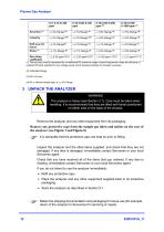
(1) The accuracy may be decreased by an additional 6% maximum range at some frequencies under the influence of radiated RF fields specified for low voltage supply which supplies buildings for domestic purposes. (4) N2 in Helium linearity spec is < ± 5% Range The analyzer is heavy (see Section 2.1). Care must be taken when handling. It is recommended that they are lifted with hands positioned on either side on the base of the chassis. Remove the analyzer and any other equipment from its packaging. Remove any protective caps from the sample gas inlets and outlets on the rear of the analyzer (see...
Open the catalog to page 13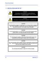
WARNING The analyzer must be installed by a suitably skilled and competent person. The following procedure must be followed to prevent a hazard. WARNING The analyzer is only suitable for installation in unclassified areas. CAUTION Do not install the analyzer in a frame/rack or on a bench which is subject to high levels of vibration or sudden jolts. If you do, sample measurements may not be accurate, or the analyzer may be damaged. CAUTION Do not install analyzer in an area where a strong electromagnetic field is present. Never use radio transmitters near the analyzer. CAUTION To avoid damage...
Open the catalog to page 14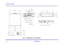
DETAIL OF REAR CONNECTION MAR< NG5 Figure 4 - DIMENSIONAL OUTLINE DRAWING 14
Open the catalog to page 15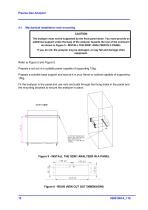
4.1 Mechanical installation rack mounting The analyzer must not be supported by the front panel alone. You must provide an additional support under the base of the analyzer towards the rear of the enclosure as shown in Figure 5 - INSTALL THE 02001 ANALYZER IN A PANEL. If you do not, the analyzer may be damaged, or may fall and damage other Refer to Figure 5 and Figure 6 Prepare a cut-out in a suitable panel capable of supporting 15kg. Prepare a suitable base support and secure it in your frame or cabinet capable of supporting 15kg. Fit the analyzer in the panel and use nuts and bolts through...
Open the catalog to page 16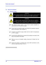
Electrical Safety WARNING Ensure that the electrical installation of the analyzer conforms with all applicable local and national electrical safety requirements. WARNING Obey the safety instructions given below when you install the analyzer; if you do not, the analyzer warranty may be invalidated, the analyzer may not operate correctly, or it may be damaged. The electrical supply coupler or plug must be easily accessible for disconnection from the electrical supply. Ensure that your electrical supply can provide the necessary maximum power consumption: refer to Section 10 All signal and electrical...
Open the catalog to page 17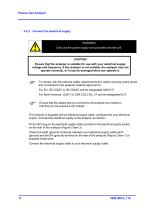
Connect the electrical supply WARNING Only use the power supply cord provided with the unit. CAUTION Ensure that the analyzer is suitable for use with your electrical supply voltage and frequency. If the analyzer is not suitable, the analyzer may not operate correctly, or it may be damaged when you operate it. To comply with the relevant safety requirements the cables carrying mains power and connected to the analyzer shall be approved to: For EU: IEC 60227 or IEC 60245 and be designated H05VV-F. For North America: UL817 or CSA C22.2 No. 21 and be designated SJT. Ensure that the cables that you...
Open the catalog to page 18All SERVOMEX catalogs and technical brochures
 Gas Guide Issue 6
74 Pages
 Product Guide Issue 10
14 Pages
 Service Guide Issue 5
12 Pages
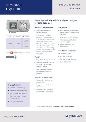 SERVOTOUGH Oxy 1810
9 Pages
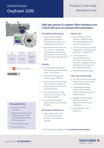 SERVOTOUGH OxyExact 2200
16 Pages
 SERVOPRO 4900 Multigas
10 Pages
 SERVOPRO PureGas
4 Pages
 DF560E Operator Manual
144 Pages
 DF-745 Operator Manual
112 Pages
 ES 39 Sustainability
11 Pages
 ES 38 Korea Special
19 Pages
 ES 37 Clean Air part II
11 Pages
 ES 36 Purity & Specialty
11 Pages
 ES 35 Photometric Analysis
11 Pages
 ES 34 70th Anniversary
15 Pages
 ES30 Air Separation Units
11 Pages
 ES 29 Clean Air
11 Pages
 ES 28 Gas Analysis Applications
11 Pages
 Sensing Technologies
13 Pages
 DF760E Operator Manual
182 Pages
 DF750 Operator Manual
112 Pages
 DF745SGMax Operator Manual
90 Pages
 DF-740 Operator Manual
87 Pages
 DF-730 Operator Manual
82 Pages
 DF560E Operator Manual 082616
146 Pages
 DF550E Operator Manual 082616
134 Pages













Archived catalogs
 Servomex Product Portfolio
2 Pages
 SERVOFLEX MiniMP 5200
7 Pages
 Servomex Product Guide - Issue 8
15 Pages
 Servomex Service Guide - Issue 3
13 Pages
 Servomex Gas Guide - Issue 4
76 Pages
 SERVOPRO HFID
4 Pages
 SERVOPRO NOx
4 Pages
 Servomex Product Guide Issue 7
13 Pages
 Servomex Service Guide Issue 2
11 Pages
 Servomex GAS GUIDE issue 3
77 Pages
 Servomex Service Portfolio
2 Pages
 SERVOTOUGH H2 Scan
2 Pages
 SERVOTOUGH SpectraScan 2400
2 Pages
 Servomex Gas Guide 2022
65 Pages





- SERVOMEX gas analyzer
- SERVOMEX concentration analyzer
- SERVOMEX monitoring analyzer
- Liquids analyzer
- Automatic analyser
- SERVOMEX benchtop analyzer
- Solids analyser
- SERVOMEX process analyzer
- SERVOMEX portable analyzer
- Continuous analyzer
- Real-time analyzer
- SERVOMEX integration analyzer
- SERVOMEX oxygen analyzer
- Laboratory analyzer
- SERVOMEX compact analyzer
- SERVOMEX digital analyzer
- Infrared analyser
- Calibration analyzer
- Waterproof analyzer
- Temperature analyzer