- Company
- Products
- Catalogs
- News & Trends
- Exhibitions
SERVOPRO NOx Operators Manual PN 221195 r0
1 /224Pages

SERVOPRO NOx Operators Manual PN 221195 r0
1 /224Pages
Catalog excerpts

Operator Manual Part Number: Revision: Language:
Open the catalog to page 1
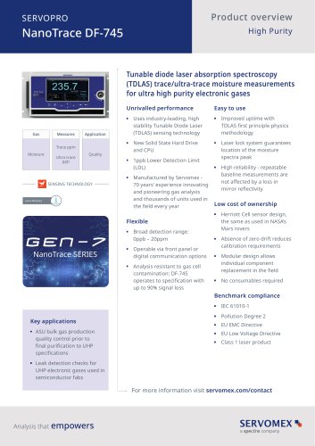
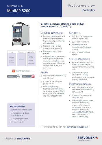
The SERVOPRO NOx is a versatile analyzer which uses the time-proven Chemiluminescence Detection (CLD) method to measure NO or NO/NO2/NOx concentrations, all in one standard package, which can also be configured with a paramagnetic oxygen (O2) sensor for emissions monitoring and control. Servomex also has a heated CLD analyzer for certification testing by heavy duty engine manufacturers that must meet the stringent requirements of US EPA 40 CFR Part 1065. Both the standard and heated analyzers can be configured with internal zero/sample/span valves and an internal sampling pump. The heated version...
Open the catalog to page 5
including not needing the high voltage required to run the PMT detector, lasts the lifetime of the instrument, and can be exposed to ambient light during servicing with no burn down time like a PMT detector. Delivering excellent linear analysis from trace levels to high ppmv concentrations (0- 3ppm to 0-3,000ppm) the SERVOPRO NOx analyzer is ideal for continuous monitoring of industrial stationary sources emissions or ambient air monitoring. Equipped with a non-depleting photodiode to detect chemiluminescent light, the fast response time of the analyzer also makes it a perfect solution for engine...
Open the catalog to page 6
Operating Principle The SERVOPRO NOx analyzer utilizes the principle of chemiluminescence for analyzing the NO, NOx or NO2 concentration within a gaseous sample. The sample enters the analyzer directly into a heated chamber and is maintained at an elevated temperature. The moisture will remain in the vapor state, ensuring no loss of the NO2. In the case of the heated NOx analyzer version, the external chiller can be used to drop the moisture content down so that the moisture does not quench the analyzer signal for those applications that require the quenching due to CO 2 and H2O to be below 2%...
Open the catalog to page 7
In the NOx mode, the sample is first routed through an internal converter which converts the NO2 in the sample to NO, then the native NO from the sample plus NO from the converted NO2 flows to the reaction chamber to react with O3. The resultant reaction is a total NO native plus the converted NO2 giving a total concentration of NOx. The NO2 is then just a simple matter of subtracting the native NO from the NOx value. Reaction Chamber The sample and O3 are delivered to the reaction chamber via the unique regulated flow system described below, and mixed together at the center of the chamber where...
Open the catalog to page 8
Flow System The basic function of the flow system is to deliver highly stablized flows of sample and air or O2 to the ozonator and reaction chamber assemblies. The EPC (electronic proportional control) valve delivers approximately 15 PSIG (standard without ozone pump option) to a pre-set capillary and consequently accurately predetermines the ozone flow rate. The air supply cylinder should be set to 25 PSIG. Sample flows through the sample EPC valve, then the NO/NO x solenoid valve, then the sample capillary and into the reaction chamber. The sample pressure is factory set to approximately 3.85...
Open the catalog to page 9
Noise Zero and Span Drift O2 Effect CH4 Effect Flow Control Sample Flow Rate Fuel Requirements Fuel Inlet Pressure Air Requirements Air Flow and Inlet Pressure Readout Less than 1% of full scale. Less than 1% of full scale per 24-hour period. Less than 2% Less than 1.2 to propane Electronic proportional pressure controller (EPC). 2.0 to 2.5 LPM 40/60 H2/He % or 100% H2 at ~250cc/min 25 psig Less than 1 ppm HC purified or synthetic air and Dew point < -10ºC. Flow ~ 450 cc/min at 25 psig As ppm or mg/m3 proportional to Methane (C1) or Propane (C3) Outputs - AK Protocol (TCP/IP and Serial RS-232)...
Open the catalog to page 10
INSTALLATION SAFET Y INFORMATION Safety Alert Temperature Hazard Electrical Shock Hazard Caution or Warning Note, Caution and Warning symbols appear on the instrument and in this manual to draw your attention to important operational and safety information. A “NOTE” marks a short message to alert you to an important detail. A “CAUTION” safety alert appears with information that is important for protecting your equipment and its performance. A “WARNING” safety alert appears with information that is important for protecting you, other people and equipment from damage. Pay especially close attention...
Open the catalog to page 11
symbol (an exclamation point in a triangle) precedes a general CAUTION or symbol (wavy vertical lines with an underscore in a triangle) precedes an symbol (a lightning bolt in a triangle) precedes an electrical shock hazard WARNING statement. elevated temperature hazard CAUTION or WARNING statement. CAUTION or WARNING statement. Some or all of the above symbols may appear in this manual or on the equipment. This manual should be consulted whenever one of these symbols is encountered on the equipment. ALWAYS REMOVE POWER BEFORE CONNECTING OR DISCONNECTING SIGNAL CABLES OR WHEN SERVICING THE EQUIPMENT...
Open the catalog to page 12
UNPACKING INSTRUCTIONS Open the shipping container and carefully remove the analyzer from the packing materials. Inspect the instrument for any sign of damage. Remove the top-cover retaining screws. Visually check for loose parts or connectors that are not properly seated. Verify that all circuit boards and circuit board connections are secure. If all internal components and their alignments look correct, re-install the cover. IMPORTANT: You should save the original shipping container your analyzer arrives in. The shipping container and packaging are specially designed to protect the analyzer...
Open the catalog to page 13
Asia Systems Engineering and Service Centre Bldg. 9, Shanghai Euromate Industrial Park No.88 Yuanshan Road Xinzhuang Industrial Park Shanghai 201108, P.R.China Tel: +86 021 6489 7570 [email protected] [email protected]
Open the catalog to page 14
RACK MOUNTING The front panel is designed for mounting into a standard 19-inch rack enclosure. Holes are located on the left and right side to allow the panel to be secured in the rack by screws. Optional rack slides allow the analyzer to be pulled out of the rack enclosure for access. REAR PANEL The rear panel includes the following: 1. Rear-panel Power ON/OFF switch. 2. Power Entry module for power connection, power switch, fuse compartment. 3. Output connectors for analog outputs and remote functions. 4. TCP/IP connection to connect to network. 5. Serial connection to connect serial connector...
Open the catalog to page 15All SERVOMEX catalogs and technical brochures
 Gas Guide Issue 6
74 Pages
 Product Guide Issue 10
14 Pages
 Service Guide Issue 5
12 Pages
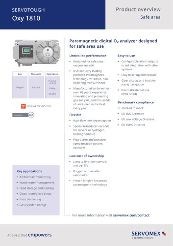 SERVOTOUGH Oxy 1810
9 Pages
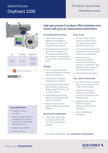 SERVOTOUGH OxyExact 2200
16 Pages
 SERVOPRO 4900 Multigas
10 Pages
 SERVOPRO PureGas
4 Pages
 DF560E Operator Manual
144 Pages
 DF-745 Operator Manual
112 Pages
 ES 39 Sustainability
11 Pages
 ES 38 Korea Special
19 Pages
 ES 37 Clean Air part II
11 Pages
 ES 36 Purity & Specialty
11 Pages
 ES 35 Photometric Analysis
11 Pages
 ES 34 70th Anniversary
15 Pages
 ES30 Air Separation Units
11 Pages
 ES 29 Clean Air
11 Pages
 ES 28 Gas Analysis Applications
11 Pages
 Sensing Technologies
13 Pages
 DF760E Operator Manual
182 Pages
 DF750 Operator Manual
112 Pages
 DF745SGMax Operator Manual
90 Pages
 DF-740 Operator Manual
87 Pages
 DF-730 Operator Manual
82 Pages
 DF560E Operator Manual 082616
146 Pages
 DF550E Operator Manual 082616
134 Pages


Archived catalogs
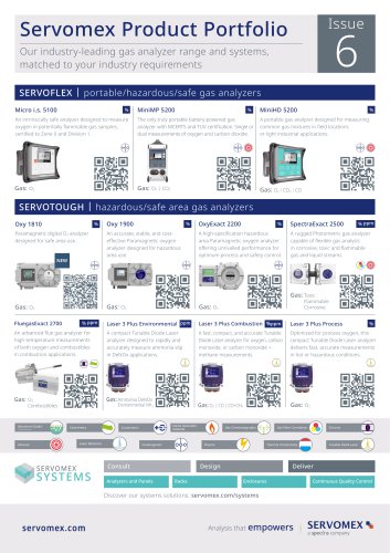
 Servomex Product Portfolio
2 Pages
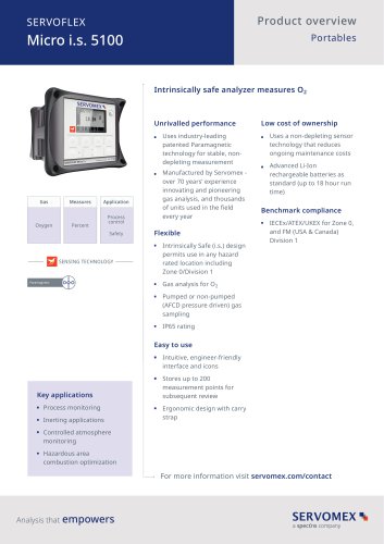
 SERVOFLEX MiniMP 5200
7 Pages
 Servomex Product Guide - Issue 8
15 Pages
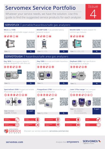
 Servomex Service Guide - Issue 3
13 Pages
 Servomex Gas Guide - Issue 4
76 Pages
 SERVOPRO HFID
4 Pages
 SERVOPRO NOx
4 Pages
 Servomex Product Guide Issue 7
13 Pages
 Servomex Service Guide Issue 2
11 Pages
 Servomex GAS GUIDE issue 3
77 Pages
 Servomex Service Portfolio
2 Pages
 SERVOTOUGH H2 Scan
2 Pages
 SERVOTOUGH SpectraScan 2400
2 Pages
 Servomex Gas Guide 2022
65 Pages


- SERVOMEX gas analyzer
- SERVOMEX concentration analyzer
- SERVOMEX monitoring analyzer
- Liquids analyzer
- Automatic analyser
- SERVOMEX benchtop analyzer
- Solids analyser
- SERVOMEX process analyzer
- SERVOMEX portable analyzer
- Continuous analyzer
- Real-time analyzer
- SERVOMEX integration analyzer
- Laboratory analyzer
- SERVOMEX oxygen analyzer
- SERVOMEX digital analyzer
- SERVOMEX compact analyzer
- Infrared analyser
- Calibration analyzer
- Waterproof analyzer
- Temperature analyzer