

- Company
- Products
- Catalogs
- News & Trends
- Exhibitions
SERVOPRO HFID Operators Manual PN 221196 r0

SERVOPRO HFID Operators Manual PN 221196 r0
The SERVOPRO HFID Analyzer Operator Manual provides detailed guidance on the operation, installation, and maintenance of HFID analyzers. It includes specifications, safety information, and operational procedures.
The manual outlines the technical specifications, including measurement capabilities, operational modes, and environmental requirements.
Installation procedures focus on safety to ensure proper setup and operation.
Guidelines are provided for safe and efficient startup and shutdown of the analyzers.
Instructions on using the keypad and navigating the menu system are included, with a menu flow chart for ease of use.
Comprehensive instructions on manual and automated calibration processes, including setup, scheduling, and error handling, are provided.
Details on setting up measurement ranges, including autorange functionality, are included.
Diagnostic tools and procedures are outlined to help troubleshoot and maintain the analyzers.
Instructions for configuring measurement settings, output settings, and programmable analogs and digitals are provided.
This section covers alarm settings, including current alarms, alarm logs, and limits for various parameters.
Information on linear coefficients and factory service options is provided for advanced maintenance.
Security features such as operator levels and password management are detailed to protect the system from unauthorized access.
Details on analog and digital interfaces, including Ethernet and serial communication specifications, are provided.
- Measures THC from 1 to 30,000 ppmc full-scale.
- Heated to 191°C for accurate "hot/wet" sampling.
- Selectable analog and digital output options.
- Automatic calibration and fast response time.
- Compliant with EPA and Euro emission standards.
The analyzer uses FID to determine hydrocarbon concentrations, with an optional methane cutter for NMHC measurement.
- Response time: T90 < 2 seconds.
- Detection limit: 10 ppb Carbon.
- Accuracy: Better than 2% of reading at or above 3.0 ppm.
- Sample flow rate: 2.0 to 2.5 LPM.
- Power requirements: 115 VAC/60 Hz or 230 VAC/50 Hz.
Safety symbols indicate important operational and safety information, with warnings about potential explosion hazards and electrical shock.
Specific fuel types are required, and technicians must be trained in handling hazardous materials.
Calibration can be done via zero and span gas ports, with pressure warnings to avoid warranty voidance.
Instructions on removing plastic caps from fittings before applying power to avoid contamination.
Use hydrocarbon-free silicone lubricant on filter housing threads to prevent seizing.
Inspect the analyzer for damage upon unpacking and report any damage to the shipping company and SERVOMEX.
The analyzer is designed for 19-inch rack mounting, with site selection guidelines to avoid direct sunlight and temperature variations.
All wiring is connected at the rear, with shielded wiring recommended for output signals.
Specifies types of gases and equipment needed, including pressure regulators and heated sample lines.
Use clean, hydrocarbon-free tubing and maintain atmospheric pressure at the sample gas bypass outlet.
Ensure all connections are leak-tight before startup and follow specific steps for shutdown.
Allow components to cool before storage and use the original shipping box if possible.
Describes the function and numeric entry modes of the keypad, including shortcuts and menu navigation.
Instructions on navigating through options and editing numbers using the keypad.
The menu flow chart helps users navigate the SERVOPRO HFID Analyzer.
Essential for setting up and performing both manual and automated calibrations.
Allows customization of the analyzer’s measurement ranges.
Provides access to diagnostic tools for troubleshooting and monitoring system parameters.
Used for configuring the analyzer’s operational settings.
Displays active alarms and allows configuration of alarm settings.
Access to maintenance and service functions.
Manages access control and security settings for the analyzer.
The starting point for accessing all operational, setup, and maintenance functions.
Displays the current gas concentration and other relevant information.
Allows selection of measurement modes: THC, CH4, or THC/CH4/NMHC.
Displays the analyzer’s model, serial number, factory settings, and software versions.
Enables control of the analyzer via keypad or remote computer.
Turns off the pump and closes solenoid valves.
Initiates the ignition sequence, requiring specific temperature conditions.
Provides access to Calibration, Setup, Diagnostics, Alarms, Service, and Security menus.
Involves zero and span calibration for each range.
Performed before span calibration, ensuring the analyzer is in the correct range.
Conducted after zero calibration, ensuring the span gas concentration matches the certificate value.
Involves setting up the analyzer for span and zero calibrations.
Allows use of the same calibration setup as in SINGLE MODE or creation of correction factors for CH4 response.
Involves a timed zero calibration followed by a timed span calibration.
Includes seven steps: purging, calibrating, verifying zero and span values, and purging with sample gas.
Provides parameters for successful calibration.
Allows automated calibrations using the analyzer’s internal clock.
Operators can select the range, mode, and calibration gases in the AutoCal Parameter screen.
Depends on how gases are introduced into the analyzer.
Feature lets the operator choose between calibration or checking the calibration.
Determines the duration of Zero and Span cycles during sequenced auto calibration.
Define the maximum acceptable error limits for zero and span gases.
Allows operators to define acceptable tolerances for Absolute and Relative deviations.
Sets allowable tolerances during the Verifying step of sequenced calibration.
Holds analog outputs to the last measured value during calibration.
Allow tracking of changes from factory and previous calibrations.
Allows viewing of Zero and Span Deviations from Manual Calibrations.
Operators can view zero or span verifying deviations taken during sequenced and auto calibrations.
Offset is the difference between factory zero and zero calibration value, while Gain is stored during span gas calibration.
Operators can reset Offsets, Gains, Linear Coefficients, and CH4 Factors to factory defaults.
Operators can change Range Limits, toggle Auto Range, and adjust Auto Range Switch Points.
The Diagnostics menu provides access to key troubleshooting screens.
These screens display temperatures, pressures, and EPC voltage percentages with alarm limits.
This diagnostic tool shows detector Raw Volts and Calculated Concentrations.
Outlines the procedures for calibrating the SERVOPRO HFID Analyzers.
Instructions are provided for accessing the I/O Status menu to view the status of digital outputs and inputs.
Details how to access the Analyzer Digital Outputs status screen.
Explains how to access and interpret the status of digital inputs.
Guidance on viewing the status of programmable digital outputs.
Instructions for accessing the Status Line menu to view and change the AK Protocol status.
Provides access to various settings including Measure Settings, Output Settings, TCP/IP parameters, and more.
Allows operators to change parameters such as Averaging Time, THC/CH4/NMHC mode times, and CH4 Correction Factors.
Explains how to set the averaging time for measured concentrations.
Instructions for setting purge and integration times between THC and CH4 cycles.
Intended for advanced operators to adjust offsets between THC and CH4 modes.
Allows operators to configure programmable analog and digital outputs.
Operators can view or change analog output signals, scaling, and adjustments.
Details how to assign signals to programmable analog outputs.
Instructions for scaling analog outputs to specific values.
Explains how to force analog outputs to specific percentages of full scale for testing purposes.
Allows operators to set the output to either mA or voltage and calibrate the outputs.
Allows operators to assign digital outputs to specific alarms or statuses.
Operators can assign digital outputs to specific alarms or statuses.
Allows operators to choose whether to hold or clear a triggered alarm.
Allows operators to test digital outputs to ensure proper functionality.
Used to set up communication between the analyzer and a computer.
Data logging can be turned on for troubleshooting purposes.
Operators can set parameters for the analyzer's startup.
Allows operators to set the internal clock for auto calibrations and data time stamping.
Provides access to current alarms, an alarm log, and alarm limits.
Operators can set upper and lower limits for temperature, pressure, EPC voltage, and gas concentration alarms.
Instructions for setting concentration alarm limits.
The Alarm Display can be toggled on or off.
Provides access to linear coefficients and factory service options.
Operators can adjust linear coefficients to optimize analyzer linearity.
Allows operators to set access levels and change passwords.
The analyzer supports analog and digital interfaces, with options for voltage or current outputs.
Analog outputs can be configured for different voltage or current ranges.
The RS232 interface allows remote control via a 9-pin connector.
Commands begin with STX and end with ETX, with specific formatting for function bytes and parameters.
Commands are structured with specific byte sequences, starting with an STX and ending with an ETX.
Includes Scan Commands, Control Commands, and Configuration Commands.
Outlines potential errors and provides error codes for troubleshooting.
Commands without errors will receive an acknowledgment echoing the function code and error status.
Includes a list of abbreviations used in commands.
Detailed descriptions of specific commands and their expected responses are provided.
A comprehensive list of error numbers is provided.
Covers features like auto calibration parameters, polynomial coefficients, and TCP/IP settings.
- Pause Mode (SPAU): Shuts off the flame.
- Standby Mode (STBY): Ignites if Auto-ignite is on.
- Zero Calibration (SNGA): Sets the analyzer to zero calibration mode.
- Span Calibration (SEGA): Sets the analyzer to span calibration mode.
- Purge Mode (SSPL): Opens the purge gas valve.
- Automatic Calibration (SATK): Starts automatic calibration for all available ranges.
- Measuring Range (SEMB): Sets the measuring range and disables auto range.
- Auto Range (SARE/SARA): Turns auto range on or off.
- Remote and Manual Modes (SREM/SMAN): Sets the analyzer to remote or manual mode.
- Measure Mode (SMGA): Starts measuring and turns on pumps if fitted.
- Save Measured Values (SNKA/SEKA): Saves measured values as new offset or span values.
- Data Streaming (SUDP): Starts or stops UDP data streaming.
- Reset Offsets and Gains (SVZS): Resets all range offsets to 0 and gains to 1.
- Set Calibration Gas Flow (SENT): Configures pumps or valves for calibration gas flow.
- Span Gas Concentration (EKAK): Sets the four span gas concentration values.
- Measuring Range Limits (EMBE): Sets the full scale limits for measuring ranges.
- Auto Calibration Times (EFDA): Configures purge and verification times for auto calibration.
- System Time (ESYZ): Sets the system time.
- Diagnostic Alarm Limits (EDAL): Configures diagnostic alarm limits.
- Modbus Protocol: Describes the encapsulation of Modbus requests and responses over TCP/IP.
- MBAP Header: Contains fields for transaction identification, protocol identification, length, and unit identification.
- Function Codes: Includes codes for reading status bits and floating-point numbers.
- Commands are structured with specific codes and parameters for precise control and configuration of the analyzer.
- Calibration and measurement modes are critical for maintaining accuracy and reliability.
- Communication protocols ensure seamless data exchange and remote control capabilities.
- Code 04: Used to read input registers.
- Code 05: Used to write a single output to ON or OFF.
- Code 06: Used to write a single holding register.
- Code 16: Used to write a single floating point register.
- Code 26: A non-standard code used to read an ASCII string.
- Read Coils: Lists coil numbers and descriptions for reading data.
- Write Coils: Lists coil numbers and descriptions for writing data.
- Read Floating Point: Lists register numbers and descriptions for reading floating point data.
- Write Floating Point: Lists register numbers and descriptions for writing floating point data.
Catalog excerpts

SERVOPRO HFID Analyzer Operator Manual Part Number: SERVOPRO HFID Analyzers
Open the catalog to page 1
SERVOPRO HFID Analyzers
Open the catalog to page 5
Description The Servomex SERVOPRO HFID analyzer is an exceptionally accurate Flame Ionization Detection (FID) gas analyzer designed for measuring hydrocarbons concentrations in gaseous samples. The analyzer utilizes a highly sensitive flame ionization detector for measuring volatile hydrocarbon concentrations in industrial stationary source or mobile source (such as vehicle or engine certification) emission applications. The SERVOPRO HFID family of heated analyzers includes the standard unit reporting only total hydrocarbon (THC) or it can be equipped with a non-methane hydrocarbon “cutter” that...
Open the catalog to page 6
Selectable analog output options: current in mA or volts in DC of 0 -1, 0-5 or 0 - Digital Output options: Modbus via TCP/IP, and AK Protocol via RS232 or Automatic fuel and air shutoffs Automatic calibration and ranging Fast response time ETL listed – conforms to UL STD 61010-1, certified to CAN/CSA C22.2 STD 61010.1 EPA 40 CFR Part 1065/1066 and Euro VI HD and Euro 6 LD compliant configurations The analyzer offers four basic factory ranges 30/300/3,000/30,000 (C1 as ppm or mg/m 3) or 10/100/1,000/10,000 (C3 as ppm or mg/m 3) which can be scaled and preset to either ppm or mg/m3 at the factory...
Open the catalog to page 7
ensure that the moisture content does not fluctuate more than a few % and that the O 2 levels in the sample are always maintained at 10% or above in order for the FID to remain lit. If these conditions are not met then the analyzer performance will be adversely affected and/or it may damage the cutter material. If using 100% H2 fuel and running the CH4 mode in the NMHC version, make sure the moisture content does not fluctuate more than a few % or lower and that the O2 levels are always maintained at 10% or CAUTION above, if not then the analyzer performance will be adversely affected and/or...
Open the catalog to page 8
processing the data according to the requirements as prescribed by the regulatory body. In many cases this is not a simple subtraction process, so please consult your regulatory agency to determine how you are required to obtain the final NMHC value. A heated oven (191°C) contains a burner and an optional heated pump. The small flame of the burner is elevated and sustained by the regulated flows of air and either pure hydrogen or a 40/60 mixture of hydrogen and helium (a hydrogen / nitrogen option is available but is not offered as a standard product – consult Servomex if this option is required)....
Open the catalog to page 9
Heated Oven The heated sample gas is maintained above its dew point by a self-contained internal oven. The oven temperature is adjusted at the factory to be controlled at 191°C. The sample gas is maintained at this elevated temperature until it exits the analyzer’s bypass outlet, preventing any loss of hydrocarbon concentration in the sample due to condensation. Because the sample gas is analyzed HOT/WET you must make sure to keep the vent tubing on the bypass outlet short and pointed downwards to avoid plugging the vent line with condensed moisture. Flow System Combustion air and fuel used by...
Open the catalog to page 10
Flow Control Sample Flow Rate Fuel Requirements Fuel Inlet Pressure Zero and Span Gas Requirements (for 100% H2 Version) Air Flow and Inlet Pressure Readout Outputs Diagnostics Special Features FID Ignition Sample Temperature Ambient Temperature Ambient Humidity Warm-up Time Fittings Power Requirements Dimensions Weight SERVOPRO HFID Analyzers Electronic proportional pressure controller (EPC) 2.0 to 2.5 LPM THC Version (40/60)% H2/He (140cc/min) or 100% H2 (60cc/min) NMHC Version (40/60)% H2/He or 100% H2 (250cc/min) 25 psig For the 100% H2 fuel version the sample gas and calibration / span gases...
Open the catalog to page 11
INSTALLATION SAFET Y INFORMATION Safety Alert Temperature Hazard Caution or Warning Electrical Shock Hazard Caution or Warning Note, Caution and Warning symbols appear on the instrument and in this manual to draw your attention to important operational and safety information. A “NOTE” marks a short message to alert you to an important detail. A “CAUTION” safety alert appears with information that is important for protecting your equipment and its performance. A “WARNING” safety alert appears with information that is important for protecting you, other people and equipment from damage. Pay especially...
Open the catalog to page 12
Some or all of the above symbols may appear in tis manual or on the equipment. This manual should be consulted whenever one of these symbols is encountered on the equipment. WARNING: ALWAYS REMOVE POWER BEFORE CONNECTING OR DISCONNECTING SIGNAL CABLES OR WHEN SERVICING THE EQUIPMENT. Potential Explosion Hazard WARNING: This analyzer uses a fuel that contains a FLAMMABLE LEVEL OF HYDROGEN. Any leakage from this fuel can result in an explosion. Carefully check the fuel supply system for leaks upon installation, before initial startup, during any maintenance or after the integrity of the system...
Open the catalog to page 13
Fuel Requirements The SERVOMEX factory configures the SERVOPRO HFID analyzer for either 100% Hydrogen or 40%/60% Hydrogen/Helium fuel. Please make sure to use the correct fuel as specified on the fuel label affixed to the back panel of the analyzer. WARNING: Use of incorrect fuel will damage the instrument and could cause an explosion. Before initial startup, carefully check the fuel supply system to the analyzer for leaks. The operating technician should be properly trained for working with hazardous materials. Potential Sample Pump Damage The analyzer can be calibrated using the optional zero...
Open the catalog to page 14
2. Always use a second wrench on the body of the filter housing when attempting to inspect or replace the filter. 3. Always allow the filter housing to cool to room temperature before attempting any maintenance. WARNING: Never attempt to disassemble or reassemble the filter housing while it is hot. 4. The sealing of the filter housing is accomplished with the o-ring. Do not over tighten. Re-assembly of the filter housing should be sealed just past finger-tight and only when the filter housing is at room temperature. Unpacking Instructions Open the shipping container and carefully remove the analyzer...
Open the catalog to page 15All SERVOMEX catalogs and technical brochures
 Gas Guide Issue 6
74 Pages
 Product Guide Issue 10
14 Pages
 Service Guide Issue 5
12 Pages
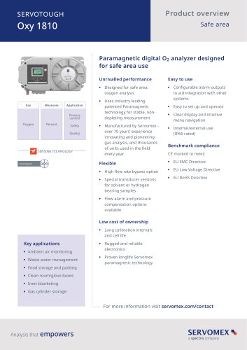 SERVOTOUGH Oxy 1810
9 Pages
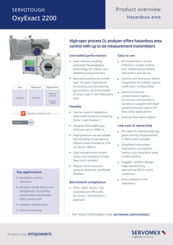 SERVOTOUGH OxyExact 2200
16 Pages
 SERVOPRO 4900 Multigas
10 Pages
 SERVOPRO PureGas
4 Pages
 DF560E Operator Manual
144 Pages
 DF-745 Operator Manual
112 Pages
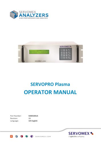 SERVOPRO Plasma Operator Manual
78 Pages
 ES 39 Sustainability
11 Pages
 ES 38 Korea Special
19 Pages
 ES 37 Clean Air part II
11 Pages
 ES 36 Purity & Specialty
11 Pages
 ES 35 Photometric Analysis
11 Pages
 ES 34 70th Anniversary
15 Pages
 ES30 Air Separation Units
11 Pages
 ES 29 Clean Air
11 Pages
 ES 28 Gas Analysis Applications
11 Pages
 Sensing Technologies
13 Pages
 DF760E Operator Manual
182 Pages
 DF750 Operator Manual
112 Pages
 DF745SGMax Operator Manual
90 Pages
 DF-740 Operator Manual
87 Pages
 DF-730 Operator Manual
82 Pages
 DF560E Operator Manual 082616
146 Pages
 DF550E Operator Manual 082616
134 Pages











Archived catalogs
 Servomex Product Portfolio
2 Pages
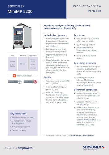 SERVOFLEX MiniMP 5200
7 Pages
 Servomex Product Guide - Issue 8
15 Pages
 Servomex Service Guide - Issue 3
13 Pages
 Servomex Gas Guide - Issue 4
76 Pages
 SERVOPRO HFID
4 Pages
 SERVOPRO NOx
4 Pages
 Servomex Product Guide Issue 7
13 Pages
 Servomex Service Guide Issue 2
11 Pages
 Servomex GAS GUIDE issue 3
77 Pages
 Servomex Service Portfolio
2 Pages
 SERVOTOUGH H2 Scan
2 Pages
 SERVOTOUGH SpectraScan 2400
2 Pages
 Servomex Gas Guide 2022
65 Pages





- SERVOMEX concentration analyzer
- SERVOMEX monitoring analyzer
- Liquids analyzer
- Automatic analyser
- SERVOMEX benchtop analyzer
- Solids analyser
- SERVOMEX process analyzer
- SERVOMEX portable analyzer
- Continuous analyzer
- Real-time analyzer
- SERVOMEX integration analyzer
- SERVOMEX oxygen analyzer
- Laboratory analyzer
- SERVOMEX compact analyzer
- SERVOMEX digital analyzer
- Infrared analyser
- Calibration analyzer
- Waterproof analyzer
- Temperature analyzer