- Company
- Products
- Catalogs
- News & Trends
- Exhibitions
SERVOPRO Chroma Operator Manual 04400001A_6
1 /139Pages

SERVOPRO Chroma Operator Manual 04400001A_6
1 /139Pages
Catalog excerpts

SERVOPRO Chroma OPERATOR MANUAL OPERATOR MANUAL Part Number: Revision: Language:
Open the catalog to page 1
SERVOPRO CHROMA Gas Analyser
Open the catalog to page 2
SERVOPRO CHROMA Gas Analyser TABLE OF CONTENT Section
Open the catalog to page 3
SERVOPRO CHROMA Gas Analyser
Open the catalog to page 4
SERVOPRO CHROMA Gas Analyser
Open the catalog to page 5
SERVOPRO CHROMA Gas Analyser
Open the catalog to page 6
SERVOPRO CHROMA Gas Analyser LIST OF TABLES Table name
Open the catalog to page 7
SERVOPRO CHROMA Gas Analyser LIST OF FIGURES Figure name
Open the catalog to page 8
SERVOPRO CHROMA Gas Analyser
Open the catalog to page 9
SERVOPRO CHROMA Gas Analyser 1 DESCRIPTION AND DEFINITIONS 1.1 Scope of this manual This manual provides installation, operation and routine maintenance instructions for the SERVOPRO Chroma Online Trace Gas analyser, abbreviated to “SERVOPRO Chroma” or “analysers” where applicable in the reminder of this manual. 1.2 Safety information Read this manual and ensure that you fully understand its content before you attempt to install, use or maintain the SERVOPRO Chroma. Important safety information is highlighted in this manual as WARNINGs and CAUTIONs, which are used as follows. WARNING Warnings...
Open the catalog to page 10
SERVOPRO CHROMA Gas Analyser 1.3 Description of Chroma Gas Analyser 1.3.1 Introduction The SERVOPRO Chroma is a 19” rack mounted online trace gas analyser, shipped pre-configured and requires little operator intervention. The analyser measures impurities in bulk gases, such as H2, O2, N2, Ar, CH4, CO, CO2 and NMHC impurities in H2, O2, N2, Ar or He background gas. The analyser configuration - form factor, detector(s), column(s), and valves - is application dependent. The analyser can be fitted with a number of detector types – Plasma Emission Detector (PED), TCD (Thermal Conductivity Detector),...
Open the catalog to page 11
SERVOPRO CHROMA Gas Analyser 1.3.2 Plasma Emission Detector (PED) The plasma emission detector (PED) is based on a spectroscopic emission cell, which is an established technique to measure impurities from the ppb to ppm level. The characteristics which make the plasma system stable and selective are the frequency, intensity, regulation, the coupling technique and the focusing (stabilizing) electrodes. The carrier gas flows at atmospheric pressure through a proprietary pure quartz cell. The cell is submitted to a high frequency high intensity electromagnetic field. This ionizes the carrier gas...
Open the catalog to page 12
SERVOPRO CHROMA Gas Analyser 1.3.4 Thermal Conductivity Detector (TCD) The Thermal Conductivity Detector (TCD) is a universal technique suitable to determine mixture of gases at percentage levels. The TCD compares the thermal conductivity of two gas flows – the pure carrier (reference) gas and the impurity eluting from the GC column. Changes in the temperature of the electricallyheated wires in the detector are affected by the thermal conductivity of the gas which flows around this. The changes in this thermal conductivity are sensed as a change in electrical resistance and are measured. The...
Open the catalog to page 13
SERVOPRO CHROMA Gas Analyser 1.3.8 I/O board The I/O board holds all the I/O functions of the instrument, shown in the table below. Digital I/O ❖ 6 oven temperature RTD input ❖ 8 isolated process 4-20 mA output 1 isolated digital input 8 remote range dry contact outputs 2 alarm dry contact outputs 1 system status dry contact output 1 extra relay 10 G.C. valve contact outputs 6 oven power relays All digital inputs and outputs, analogue inputs and outputs are transient and fuse protected. The I/O board is connected to an external 40 pin I/O connector through a flat cable connector The 40 pin I/O...
Open the catalog to page 14
SERVOPRO CHROMA Gas Analyser 1.4 Description of Analyser Rear Connections 1.4.1 SERVOPRO Chroma Complete Rear Connections Figure 1 : SERVOPRO Chroma complete rear connections This rear panel is fitted to the master chassis, and to the secondary chassis in a system with a stand-alone PC. 1. Power inlet with switch and fuse 2. Gas trap inlet 3. RS-232/RS-485 socket 4. Auxiliary oven 5. RS-485 socket 6. Gas trap outlet 7. Ethernet port 8. USB port 9. Analogue 4-20 mA outputs 10. Digital outputs 11. Digital input 12. Earth terminals for cable screens 13. Carrier gas inlet to detector 1 14. Carrier...
Open the catalog to page 15
SERVOPRO CHROMA Gas Analyser 1.4.2 SERVOPRO Chroma Reduced Rear Connections Figure 2 : SERVOPRO Chroma reduced rear connections This rear panel is fitted to the secondary chassis in a system with a master chassis. 1. Power inlet with switch and fuse 2. RS-485 3. Carrier gas inlet 4. Carrier gas vent 5. Detector 1 vent 6. Detector 2 vent 7. Sample gas vent 8. Sample gas inlet 1 (process) 9. Sample gas inlet 2 (span) Note: the RS-232 port is replaced with a RS-485 port on Secondary Chassis 1 on an analyser with multiple secondary chassis.
Open the catalog to page 16
SERVOPRO CHROMA Gas Analyser Gas connections when FID Detector is fitted Figure 3 : Gas connections when FID Detector fitted When a FID detector is installed in the SERVOPRO Chroma, the function of some of the rear gas connections are changed, as shown in Figure 3. 1. 2. 3. 4. FID Detector vent Fuel inlet Air inlet H2 contacts to control the fuel shut-off valve (see section 6.2.7) See Section 12 for more information on the FID detector.
Open the catalog to page 17
SERVOPRO CHROMA Gas Analyser 1.5 Auxiliary Oven 1.5.1 Description of Auxiliary Oven The Auxiliary Oven is an external module used when analysing N2 impurity in either H2 or O2 background gas. It is connected to the specific channel making the N2 determination, and removes the small volume of interfering background gas which has co-eluted with the N2 prior to the passing to the detector. 1.5.2 Auxiliary Oven Rear Connections Figure 4 : Auxiliary Oven rear connections 1. Power inlet 2. Oven inlet (connect to Trap In gas connector on Master or Secondary Chassis) 3. Oven outlet (connect to Trap Out...
Open the catalog to page 18
SERVOPRO CHROMA Gas Analyser Standalone PC Rear Connections Figure 5 : Standalone PC rear connections Power inlet with switch and fuse RS-232 port for remote terminal (marked “AUX”) RS-232 port for secondary unit (marked “TO ANALYSER”) USB port Ethernet port CAUTION To comply with the requirements of the EU EMC Directive, data cables used with the standalone PC (USB, Ethernet,) must be fitted with ferrite beads (Würth 74271131 or 74271221, depending on cable size), which should be clamped around 2 turns of cable. CAUTION To comply with the requirements of the EU EMC Directive, the front USB port...
Open the catalog to page 19All SERVOMEX catalogs and technical brochures
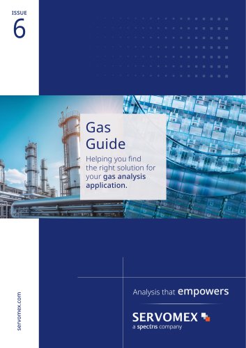 Gas Guide Issue 6
74 Pages
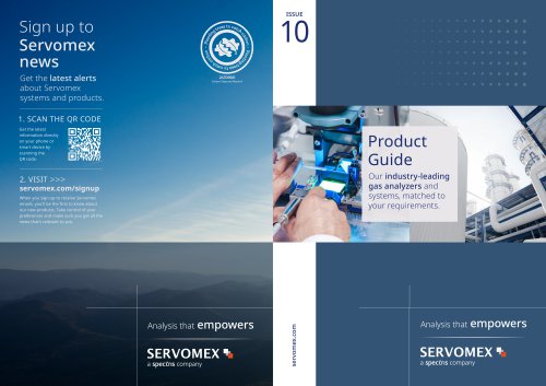 Product Guide Issue 10
14 Pages
 Service Guide Issue 5
12 Pages
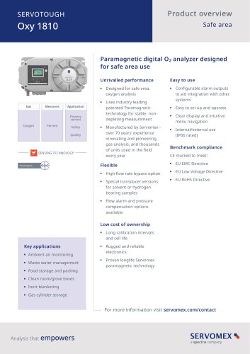 SERVOTOUGH Oxy 1810
9 Pages
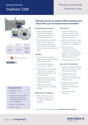 SERVOTOUGH OxyExact 2200
16 Pages
 SERVOPRO 4900 Multigas
10 Pages
 SERVOPRO PureGas
4 Pages
 DF560E Operator Manual
144 Pages
 DF-745 Operator Manual
112 Pages
 ES 39 Sustainability
11 Pages
 ES 38 Korea Special
19 Pages
 ES 37 Clean Air part II
11 Pages
 ES 36 Purity & Specialty
11 Pages
 ES 35 Photometric Analysis
11 Pages
 ES 34 70th Anniversary
15 Pages
 ES30 Air Separation Units
11 Pages
 ES 29 Clean Air
11 Pages
 ES 28 Gas Analysis Applications
11 Pages
 Sensing Technologies
13 Pages
 DF760E Operator Manual
182 Pages
 DF750 Operator Manual
112 Pages
 DF745SGMax Operator Manual
90 Pages
 DF-740 Operator Manual
87 Pages
 DF-730 Operator Manual
82 Pages
 DF560E Operator Manual 082616
146 Pages
 DF550E Operator Manual 082616
134 Pages


Archived catalogs
 Servomex Product Portfolio
2 Pages
 SERVOFLEX MiniMP 5200
7 Pages
 Servomex Product Guide - Issue 8
15 Pages
 Servomex Service Guide - Issue 3
13 Pages
 Servomex Gas Guide - Issue 4
76 Pages
 SERVOPRO HFID
4 Pages
 SERVOPRO NOx
4 Pages
 Servomex Product Guide Issue 7
13 Pages
 Servomex Service Guide Issue 2
11 Pages
 Servomex GAS GUIDE issue 3
77 Pages
 Servomex Service Portfolio
2 Pages
 SERVOTOUGH H2 Scan
2 Pages
 SERVOTOUGH SpectraScan 2400
2 Pages
 Servomex Gas Guide 2022
65 Pages


- SERVOMEX gas analyzer
- SERVOMEX concentration analyzer
- SERVOMEX monitoring analyzer
- Liquids analyzer
- Automatic analyser
- SERVOMEX benchtop analyzer
- Solids analyser
- SERVOMEX process analyzer
- SERVOMEX portable analyzer
- Continuous analyzer
- Real-time analyzer
- SERVOMEX integration analyzer
- SERVOMEX oxygen analyzer
- Laboratory analyzer
- SERVOMEX digital analyzer
- SERVOMEX compact analyzer
- Infrared analyser
- Calibration analyzer
- Waterproof analyzer
- Temperature analyzer