- Company
- Products
- Catalogs
- News & Trends
- Exhibitions
SERVOFLEX Micro i.s. 5100 Operator Manual 05110001A_10
1 /86Pages

SERVOFLEX Micro i.s. 5100 Operator Manual 05110001A_10
1 /86Pages
Catalog excerpts

OPERATOR MANUAL Part Number: Revision: Language:
Open the catalog to page 1
LIST OF CONTENTS Section Page DESCRIPTION AND DEFINITIONS. . . . . . . . . . . . . . . . . . . . . . . . 1 Scope of this manual . . . . . . . . . . . . . . . . . . . . . . . . . . . . . . . . . . . Safety information. . . . . . . . . . . . . . . . . . . . . . . . . . . . . . . . . . . . . . Description . . . . . . . . . . . . . . . . . . . . . . . . . . . . . . . . . . . . . . . . . . . Sample measurement configurations . . . . . . . . . . . . . . . . . . . . . . . Other product options . . . . . . . . . . . . . . . . . . . . . . . . . . . . . . . . . . . General . . . . . . . . . . . . . . ....
Open the catalog to page 3
CONTENTS (CONTINUED) Section Locating the 5100 i.s. and switching on . . . . . . . . . . . . . . . . . . . . . Calibrating the 5100 i.s. . . . . . . . . . . . . . . . . . . . . . . . . . . . . . . . . . Taking sample readings. . . . . . . . . . . . . . . . . . . . . . . . . . . . . . . . . Correcting oxygen measurement for different background gases . Overview of measurement errors . . . . . . . . . . . . . . . . . . . . . . . . . Entering a cross-interference compensation . . . . . . . . . . . . . . . . . Selecting display units . . . . . . . . . . . . . . . . . . . . . . . . . . . . . . . ....
Open the catalog to page 4
CONTENTS (CONTINUED) Section DISPLAY UNIT CONVERSION FACTORS . . . . . . . . . . . . . . . . . . 67 OPTIONAL GAS PROBE ACCESSORY . . . . . . . . . . . . . . . . . . . . 68 Overview . . . . . . . . . . . . . . . . . . . . . . . . . . . . . . . . . . . . . . . . . . . . 68 Preparing for use . . . . . . . . . . . . . . . . . . . . . . . . . . . . . . . . . . . . . . 68 Using the probe . . . . . . . . . . . . . . . . . . . . . . . . . . . . . . . . . . . . . . . 68 Additional maintenance . . . . . . . . . . . . . . . . . . . . . . . . . . . . . . . . . 68 Additional spares . . . . . . . . . . . ....
Open the catalog to page 5
This page intentionally blank.
Open the catalog to page 6
Scope of this manual This manual provides installation, operation and routine maintenance instructions for the Servomex 5100 i.s. Portable Gas Analyser, abbreviated to "5100 i.s." in the remainder of this manual. Safety information Read this manual and ensure that you fully understand its content before you attempt to install, use or maintain the 5100 i.s. Important safety information is highlighted in this manual as WARNINGs and CAUTIONs, which are used as follows: WARNING Warnings highlight specific hazards which, if not taken into account, may result in personal injury or death. CAUTION Cautions...
Open the catalog to page 7
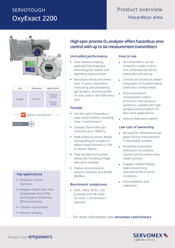
Gas sample measurements are shown on the 5100 i.s. display (see Section 4.2). The 5100 i.s. is supplied with an internal rechargeable battery, and with a power supply unit: • The 5100 i.s. is suitable for sampling gases in hazardous areas (refer to Section 2.9) when the 5100 i.s. is operated as a portable unit (powered by the battery) and is disconnected from the power supply unit. • When it is connected to the power supply unit and the power supply unit is connected to the electrical supply, the 5100 i.s. must only be used (to charge/ recharge the battery or set up the analyser) in safe areas....
Open the catalog to page 8
Soft key 1 Soft key 2 Soft key 3 Soft key 4 Sample gas label * Display Power On/Off key Fault LED (amber) Alarm LED (red) Sample pump LED (green) † Sample pump key † * The legend on the label shows the sample gas for which the 5100 i.s. is configured. † Only active if the 5100 i.s. has an optional internal sample pump.
Open the catalog to page 9
Description Filter retaining cap Breather vent Rechargeable battery cover
Open the catalog to page 10
Description Sample gas inlet Sample gas outlet Description Bypass gas outlet DC power inlet
Open the catalog to page 11
SPECIFICATION WARNING You must install and use the 5100 i.s. in accordance with the requirements of this section and subsequent sections of the manual. If you do not, the protection facilities incorporated into the design of the 5100 i.s. may not operate as intended, sample gas measurements may not be accurate, or the 5100 i.s. may be damaged. General Dimensions (width x depth x height) Mass (minimum to maximum) Electrical supply requirements Power supply unit 5100 i.s. * As supplied by the power supply unit (through a centre pin +ve connector). 2.2 Environmental limits WARNING The 5100 i.s....
Open the catalog to page 12
Calibration gases WARNING If the 5100 i.s. is specified for use with carbon monoxide or carbon dioxide, the concentrations of the gases used may be above their respective threshold limit values, and should therefore be considered toxic. You must therefore carry out a risk assessment before you use the 5100 i.s. with such gases. The maximum inlet pressures of such gases are: • For a 5100 i.s. with an internal sample pump: 110 kPa absolute (1.1 bar absolute, 16 psi absolute). • For a 5100 i.s. with an AFCD: 35 kPa gauge (0.35 bar gauge, 5 psi gauge). WARNING You must only use the 5100 i.s. with...
Open the catalog to page 13
Sample gases WARNING If the 5100 i.s. is specified for use with carbon monoxide or carbon dioxide, the concentrations of the gases used may be above their respective threshold limit values, and should therefore be considered toxic. You must therefore carry out a risk assessment before you use the 5100 i.s. with such gases. The maximum inlet pressures of such gases are: • For a 5100 i.s. with an internal sample pump: 110 kPa absolute (1.1 bar absolute, 16 psi absolute). • For a 5100 i.s. with an AFCD: 35 kPa gauge (0.35 bar gauge, 5 psi gauge). WARNING You must only use the 5100 i.s. with oxygen...
Open the catalog to page 14
Performance: standard oxygen sensor WARNING You must only use the 5100 i.s. with oxygen enriched sample/calibration gases (with oxygen concentrations higher than 21%) when it is located in a safe area. The display indication given below is the default indication. You can configure the 5100 i.s. to provide other display indications (see Section 6.5). Display indication Measured volume % oxygen Full Scale Range 0 to 100% oxygen: see the warning above Intrinsic error (accuracy) Zero drift per week Output fluctuation Response time # Flow variation effect Zero temperature coefficient Span temperature...
Open the catalog to page 15All SERVOMEX catalogs and technical brochures
 Gas Guide Issue 6
74 Pages
 Product Guide Issue 10
14 Pages
 Service Guide Issue 5
12 Pages
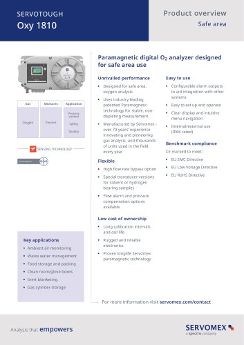 SERVOTOUGH Oxy 1810
9 Pages
 SERVOTOUGH OxyExact 2200
16 Pages
 SERVOPRO 4900 Multigas
10 Pages
 SERVOPRO PureGas
4 Pages
 DF560E Operator Manual
144 Pages
 DF-745 Operator Manual
112 Pages
 ES 39 Sustainability
11 Pages
 ES 38 Korea Special
19 Pages
 ES 37 Clean Air part II
11 Pages
 ES 36 Purity & Specialty
11 Pages
 ES 35 Photometric Analysis
11 Pages
 ES 34 70th Anniversary
15 Pages
 ES30 Air Separation Units
11 Pages
 ES 29 Clean Air
11 Pages
 ES 28 Gas Analysis Applications
11 Pages
 Sensing Technologies
13 Pages
 DF760E Operator Manual
182 Pages
 DF750 Operator Manual
112 Pages
 DF745SGMax Operator Manual
90 Pages
 DF-740 Operator Manual
87 Pages
 DF-730 Operator Manual
82 Pages
 DF560E Operator Manual 082616
146 Pages
 DF550E Operator Manual 082616
134 Pages


Archived catalogs
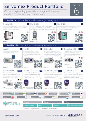
 Servomex Product Portfolio
2 Pages
 SERVOFLEX MiniMP 5200
7 Pages
 Servomex Product Guide - Issue 8
15 Pages
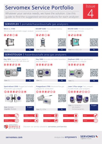
 Servomex Service Guide - Issue 3
13 Pages
 Servomex Gas Guide - Issue 4
76 Pages
 SERVOPRO HFID
4 Pages
 SERVOPRO NOx
4 Pages
 Servomex Product Guide Issue 7
13 Pages
 Servomex Service Guide Issue 2
11 Pages
 Servomex GAS GUIDE issue 3
77 Pages
 Servomex Service Portfolio
2 Pages
 SERVOTOUGH H2 Scan
2 Pages
 SERVOTOUGH SpectraScan 2400
2 Pages
 Servomex Gas Guide 2022
65 Pages


- SERVOMEX gas analyzer
- SERVOMEX concentration analyzer
- SERVOMEX monitoring analyzer
- Liquids analyzer
- Automatic analyser
- SERVOMEX benchtop analyzer
- Solids analyser
- SERVOMEX process analyzer
- SERVOMEX portable analyzer
- Continuous analyzer
- Real-time analyzer
- SERVOMEX integration analyzer
- Laboratory analyzer
- SERVOMEX oxygen analyzer
- SERVOMEX digital analyzer
- SERVOMEX compact analyzer
- Infrared analyser
- Calibration analyzer
- Waterproof analyzer
- Temperature analyzer