

- Company
- Products
- Catalogs
- News & Trends
- Exhibitions
DF760E Operator Manual

DF760E Operator Manual
The NanoTrace Dual Moisture/Oxygen Analyzer DF-760E, manufactured by Servomex Corporation, is designed under ISO-9001 quality controls and calibrated with NIST traceable gases. It requires minimal maintenance for long-term accuracy.
Inspect the packaging for damage and verify contents against the packing slip. Essential components include electrolyte, replenishment solution, power cord, USB memory stick, VCR filter gasket, aspirator, zero gas purifier, and the instruction manual. Ensure the voltage setting matches your requirements.
Proper installation and maintenance are crucial for optimal performance. Follow the manual's guidelines, focusing on Ultra-High Purity (UHP) gas handling. Maintenance includes periodic zero and span calibrations and replenishment of the oxygen sensor solution.
The manual provides detailed specifications for oxygen and moisture measurement capabilities, ensuring users understand the operational parameters and limitations.
Detailed instructions are provided for installing the analyzer, including mounting, electrical connections, and gas line setup. The start-up procedure involves setting gas pressure and flow, while shut down requires careful disconnection to maintain system integrity.
The analyzer offers various options such as key lock, operating voltage adjustments, and serial communications. It supports connections to external devices via serial ports, analog outputs, and relay ports.
The user interface includes a data display screen and keypad, with menus for moisture and oxygen control, calibration, data history, and diagnostics. The system menu allows for adjustments and testing of system components.
Guidelines are provided for sample gas flow rate and pressure, emphasizing the effects on sensor performance and the importance of leak checks. The manual also addresses the impact of background gases, pressure, and temperature on analyzer performance.
This section explains the symbols used in the manual, such as CAUTION CONSULT MANUAL, NOTE, CAUSTIC LIQUID, and ELECTRICAL SHOCK HAZARD.
Critical safety warnings include reading the manual, hazardous AC voltage, power cord safety, and specifications for a customer-supplied 220 VAC power cord.
Ensure the power cord is plugged into a properly grounded outlet and meets specific specifications, including a 250 V AC rating, 10 amperes, and an IEC60320 C13 connector.
The analyzer is factory set for either 110 or 220 VAC. Operating on a different voltage can cause damage, and changing the voltage requires returning the analyzer to the factory.
The analyzer weighs over 30 kg and should be lifted by two people using proper techniques to avoid injury. It is designed for rack mounting, and the support rails must be rated for 30 kg.
The DF-760 is intended for indoor use and should not be exposed to particulates, moisture, caustic environments, or extreme temperatures.
The electrolyte is caustic, and the Material Safety Data Sheet should be reviewed before handling. The oxygen sensor must be charged with electrolyte before use.
Do not ship the analyzer with electrolyte in the sensor. Thoroughly drain and rinse the sensor before shipping.
The DF-760 should not be used with pure oxygen. It is designed for inert, non-toxic, non-combustible gases. Special precautions are required for toxic and combustible gases.
Over-pressurizing the oxygen sensor can cause permanent damage. Limit backpressure to ±1 psig.
Route power cords and plumbing to avoid tripping hazards.
The analyzer may cause radio or television interference. If interference occurs, try reorienting the antenna, moving the instrument, or placing it on a different AC circuit.
- Oxygen: LDL of 75 ppt, resolution of 50 ppt, accuracy of ±3% or ±0.1 ppb, response time under 20 seconds, range of 0-20 ppm.
- Moisture: LDL of 200 ppt, resolution of 100 ppt, accuracy of ±3% or ±0.2 ppb, response time under 3 minutes, range of 0-20 ppm.
- General: Construction is NEMA 1.
The DF-760E is a rack-mounted device with dimensions of 19 inches wide, 10.5 inches high, and 22.5 inches deep. It features a 7.4-inch VGA color display.
The unit weighs 72 pounds (32.6 kg).
The device is designed for indoor use only, with an operating temperature range of 10°C to 40°C and a maximum altitude of 2000 meters. It can handle up to 80% humidity at 31°C, decreasing to 50% at 40°C.
The analyzer supports various gas inlets with specific pressure and flow requirements, including N2 or air for pneumatic and aspirator inlets.
The device includes alarm relays, analog outputs, and digital communications via RS-232 or RS-485. It also features audible and visual alarm status indicators.
The analyzer operates on 100 to 120 VAC or 200 to 240 VAC, with specific amperage requirements.
The installation process involves mounting the analyzer, connecting gas and power supplies, and ensuring proper handling of the electrolyte for the oxygen sensor. Specific safety precautions are outlined for handling the device and its components.
The standard vacuum source is a factory-installed aspirator requiring a regulated source of dry compressed gas.
The analyzer requires a properly grounded power connection, with specific instructions for voltage settings and cord requirements.
An optional system is available to protect against explosion hazards when using hydrogen sample gas.
The document outlines the integration of a Hydrogen Safety Service System, which is enabled by default to ensure safe operation when measuring hydrogen.
The document provides a detailed schematic of the AC power input connections, including relay configurations and key connections for various components such as the vacuum pump and analyzer.
The start-up process involves turning on the power, which initiates diagnostic procedures and a warm-up period of approximately six to nine minutes. During this time, all outputs are held to an artificial reading to prevent false data reporting. The document emphasizes the importance of setting user preferences during power-up and provides guidance on gas pressure and flow settings.
The gas delivery system is designed to maintain high standards of gas purity and delivery for ultra-trace analysis. It includes features such as a single inlet line, a bypass loop, and dead-leg free delivery. The system allows for zero and span calibration adjustments for sensors.
Proper gas pressure and flow settings are critical for the analyzer's operation. The document provides a step-by-step procedure for setting these parameters, including specific instructions for different gases like Nitrogen, Argon, Helium, and Hydrogen.
The document details the procedures for starting gas flow through the moisture and oxygen sensors, including equilibration times and pressure settings. It also highlights the importance of preventing backflow and maintaining proper pressure ranges.
A flow detection system is installed to monitor flow rates and prevent ambient air contamination in case of insufficient flow.
The zero gas purifier must be installed by the user after the analyzer is operational, as per shipping regulations.
After installation, system diagnostics should be downloaded and sent to Servomex for review to confirm proper operation and establish a baseline for future comparisons.
The document provides procedures for both short-term and long-term shutdowns, emphasizing the importance of isolating the analyzer and securing gas connections to minimize re-startup time.
Several options are available for the DF-760 analyzer, including key locks, operating voltage configurations, serial communications, analog voltage output settings, and a vacuum pump for cases where an aspirator is insufficient.
The document provides detailed specifications for the DF-760E vacuum pump, including mounting dimensions and power connections. Figures 9 and 10 illustrate the dimensions and mounting options for the vacuum pump, highlighting the various mounting points on the bracket.
The sample gas outlet connection uses a ¼ inch compression fitting labeled as the Moisture Sensor Outlet. Polyethylene tubing is used to connect the outlet fitting to the needle control valve and vacuum pump. If the Hydrogen Service Safety System is included, the outlet line must be steel.
The vacuum pump power cord connects to the power receptacle on the analyzer's rear. The pump will only activate when the main analyzer power switch is on. The voltage supplied to the pump matches the analyzer's input voltage.
The analyzer supports interfacing with external devices via rear panel ports, including alarm contacts, voltage, and current outputs. During startup, outputs are held to an artificial reading to prevent false reports. Serial communication ports (RS232C or RS485) allow interfacing with other systems, supporting up to 32 units via RS-485.
Analog voltage outputs for oxygen and moisture signals are provided, with full-scale voltage set at the factory. Two sets of 4-20 mA outputs are also available, electrically isolated from other outputs.
Eight form C relays are available for alarms, rated at 30 VDC, 1A resistive load. Relays are programmable for various conditions and are wired for Fail Safe operation.
The front panel display includes a GUI with sections for moisture and oxygen analyzers. It shows alarm status, concentration measurements, and gas pressure/flow rates. The keypad allows control of all features, with a menu structure for navigating settings.
The Moisture SubMenu controls the moisture cell operation. It includes options for isolating the sensor, controlling gas valves, and restoring gas flow. The calibration submenu provides options for zero calibrations and assessing gas purity.
The document discusses the operation and calibration of a moisture analyzer using absorption spectroscopy with wavelength modulation. It highlights that instrumental drift minimally affects moisture content results, and once factory settings are established, no further SPAN calibration is needed. However, sample line contributions can cause moisture offsets, especially at sub-ppb levels, which are challenging to eliminate.
The analyzer includes zeroing features to establish temporary performance near 0.0 ppb during the dry down process. Users can monitor the zero reference number to understand offsets induced by user zero actions.
This section describes the Check/Adjust Zero screen, which displays live moisture readings and zero gas control valve states. Users can restore factory zero settings if needed. The Active Zero Offset feature allows for temporary adjustments without affecting zero calibration.
The User Zero Offset function allows users to add a moisture ppb value to prevent negative readings. This adjustment does not affect zero calibration but is added to the calibrated zero.
Users can toggle the state of Zero Gas Control Valves from the screen, allowing for manual adjustments during the zeroing process.
The manual zero command enables interactive zeroing of the moisture cell. It requires moisture-free gas and involves observing the moisture reading until stable before accepting the new zero setting.
The AutoZero command automates the zeroing process and can be scheduled. It involves stability criteria and a pre-zero purge if needed. The process updates the Zero Reference if stability is achieved.
This setup allows for unattended zeroing at preset times, with options for pre-zero purging and setting stability criteria. Users can schedule AutoZero intervals and set timeouts for stabilization.
The Data History Screen displays moisture data in strip chart form for up to 24 hours. Users can download data to a USB stick, which includes moisture and oxygen data up to three weeks old.
This screen allows users to label data with unique location names and download specified data. Users can set locations from a list to start logging and create new files.
The view location function allows users to access stored data sorted by location. Users navigate through existing names using the Next and arrow keys, select the desired location, and press Enter to view the data. Data can be downloaded to a USB memory stick via the remote USB port.
Users can create a new location by selecting the Add Location button, entering the name using the on-screen keyboard, and confirming the entry. The new location will appear in the list of available locations.
This function removes a location from the list. Users select the location, move to Delete Location, and confirm the deletion. A confirmation box appears to finalize the action.
The View Logs menu provides access to past events related to operational changes or instrument upsets. Users can scroll through the list and return to the main display by pressing ESC.
This log records adjustments to the moisture cell zero setting, noting the date, time, and type of zero calibration (Manual or Automatic). It includes acceptance criteria and any issues encountered during the process.
The System Error Log reports functional errors and events. Errors persisting over 30 minutes trigger a system alarm. A list of error codes and descriptions is provided.
This log records the results of pump capacity tests, which assess the vacuum capability of the aspirator or pump. It helps detect trends indicating the need for pump maintenance.
The analyzer includes seven alarms for moisture concentration, temperature, pressure, and system errors. Users can set high/low setpoints and deadbands, and assign alarms to relays. Alarm conditions overwrite the moisture level readout, and users must acknowledge alarms by pressing Enter.
This setup defines the voltage or current output range for recording purposes. Users can set three ranges for auto-ranging based on analyzer readings. The In Calibration Relay signals zero calibration in progress.
The graph setup adjusts the time scale on the main data display, showing a history of moisture concentration over a chosen time interval.
Active Zero On/Off
The Active Zero Offset feature compensates for gradual zero baseline cleanup, ensuring accurate low ppb H2O readings. It automatically adjusts the offset as needed, with a maximum of 5 ppb.
The Signal Monitor displays 18 system parameters for diagnostic purposes in case of system errors.
The document outlines the installation and purging process for a gas analyzer. It emphasizes the importance of quickly installing the purifier to minimize exposure to ambient air, which can affect moisture readings. The analyzer is shipped with plumbing purged and filled with N2, and the purifier fittings are capped. A cycle purge is mandatory before use to eliminate ambient air effects. The analyzer automates the purge process by alternating gas flow through and around the purifier, which should not be used for process measurements during this time.
The pump capacity test determines the vacuum capability of the aspirator or pump. Proper flow through the analyzer depends on the balance between inlet pressure and outlet vacuum. The test is automatic, isolating the moisture cell and monitoring vacuum for 20 seconds. A pressure lower than 115 Torr is acceptable; otherwise, a failure is indicated, suggesting pump rebuilding or leak checks.
The Oxygen SubMenu allows operation of the oxygen sensor without affecting moisture cell operation. It includes options to isolate the sensor, control gas valves, and toggle sensor power. The sensor is protected from high oxygen concentrations, automatically shutting off after 20 minutes above 20 ppm. Users must manually restart the sensor after resolving high oxygen conditions.
The oxygen calibration menu includes zero calibration functions. The Check/Adjust Zero screen allows users to manage zero calibration, with options for manual and auto zeroing. Manual zeroing requires oxygen-free gas, while auto zeroing can be scheduled. The process involves stability criteria and updates the Zero Reference if successful. A relay signals calibration status, and the analog output can be frozen or updated during calibration.
The AutoZero Setup allows automatic zeroing at preset times. Users can set the next autozero time and date, with the process starting immediately if no changes are made. The setup ensures unattended zeroing of the moisture analyzer.
The document outlines the procedures for AutoZero and calibration of an oxygen sensor. The AutoZero Interval determines the frequency of zeroing the oxygen cell, with the next scheduled AutoZero automatically calculated. The AutoZero Timeout sets the stabilization period, and if not achieved, the process is aborted. The Zero Acceptance Criterion offers three stability options: Stable, Quick, and Normal, with varying precision and time requirements. A relay signals ongoing zero calibration, and the analog output can be frozen or updated during this process.
The Gas Scale Factor (GSF) corrects reported ppb for different background gases. While less critical for oxygen than moisture, adjustments may be necessary for gases like helium or hydrogen. The Span Reference value reflects deviation from factory calibration, and manual or AutoSpan checks can adjust this. The Span Gas value is entered directly, and the process involves attaching a span cylinder and setting appropriate pressures.
The AutoSpan Setup allows for automatic span calibration at preset intervals. It includes options for warning periods and timeout settings to ensure stabilization. The AutoSpan Type can either recalibrate or check if the span is within specified limits. A relay signals ongoing calibration, and the analog output can be managed similarly to AutoZero.
The document describes electronic digital filtering to smooth out noise and spikes in the output signal. Options include Normal, Low LDL, and Ultralow LDL, each offering different noise reduction and response times. A Transient Rejection algorithm can be enabled to manage signal spikes.
The Upload Sensor Data screen facilitates automatic installation of new calibration data from a USB stick. Manual data entry is also possible through the Enter Sensor Data screen. Proper installation and start-up procedures are emphasized for optimal sensor performance.
Maintenance includes logging replenishment solution additions and setting reminders. The Data History Screen displays data in strip chart form, with options to adjust the time scale and download data to a USB stick.
The Oxygen Data Downloader screen allows users to label data with unique location names and download specified data. Users can navigate through options using the Next key and arrow keys to select locations, view data, and manage location entries.
Users can set, view, add, or delete locations. Setting a location starts a new logging process, while changing locations ends the previous file. Viewing locations allows users to access stored data, which can be downloaded to a USB stick. Adding a location involves entering a new name, and deleting a location requires confirmation.
Users can review logged activities or alarm events in various categories, including Oxygen Zero Log, Span Log, Replenishment Solution Addition Log, OverRange/Sensor Off Log, and Over Temperature Log. Each log provides specific details about the events, such as calibration adjustments and sensor status.
The analyzer includes eight alarms for oxygen concentration, temperature, low flow, and electrolyte condition. Users can set high and low setpoints, deadbands, and assign alarms to relays. An additional alarm monitors the cabinet exhaust fan status when hydrogen is present in the background gas matrix.
This setup defines the zero and full-scale output for recorders, with three ranges available. The analyzer auto-ranges between outputs based on current readings. Users can enable a calibration relay and choose to freeze or update the analog output during calibration.
The Graph Setup allows users to adjust the time scale on the analyzer's front display, showing a history of concentration data over a specified time interval. The Y-axis auto-ranges based on current data.
The diagnostics menu provides read-only parameters for electrolyte level, oxygen cell temperature, and gas flow. Temperature compensation can be adjusted manually if automatic settings do not suffice. The Active Zero Offset feature automatically compensates for gradual zero baseline cleanup, ensuring accurate low ppb O2 readings.
The Active Zero Offset starts at 0.00 ppb and increments automatically to adjust readings. It resets to 0.00 ppb after each User Zero Calibration. It operates effectively when the zero baseline falls at less than 0.1 ppb/hr. If the offset reaches 3 ppb, a warning prompts a zero calibration. The maximum offset is 3 ppb, and further downward trends result in negative readings until recalibration.
The System menu manages operations outside specific sensors, offering higher-level user options.
This function isolates the analyzer for shipping or movement, taking 40 seconds to complete. The Restore Sample Gas Flow command returns the analyzer to normal operation.
This command restores gas flow after isolation, ensuring outlet pressure is at or below cell pressure to prevent back diffusion.
The Gas Scale Factor (GSF) is crucial for accurate results, accounting for different absorption and diffusion features in buffer gases. The default is 100% N2, with a GSF of 1.00. Changes in buffer gas require GSF adjustments.
The analyzer monitors exhaust fans, and if hydrogen is detected and a fan fails, the analyzer isolates automatically, displaying a "Fan Failure" message.
This screen monitors gas delivery system valves, indicating closed valves with an 'X'.
This system prevents contamination when gas flow is lost, isolating gas panel valves and displaying a backflow prevention message.
Users can modify the display screen contrast using the Adjust Contrast screen.
This subroutine sets default states during power-up, useful for protecting sensors or configuring for rapid transfer and measurement.
The Test Relays screen ensures moisture and oxygen relays function properly, allowing users to activate or deactivate relays as needed.
This screen calibrates moisture and oxygen analog recorder outputs, ensuring output matches entered values.
The Date/Time screen sets calendar and clock parameters, requiring manual adjustment for daylight savings.
The Communications screen sets parameters for serial PC communications, including baud rate selection.
Internal system data files can be downloaded to a USB stick for evaluation if problems arise.
The USB port is located behind the front door on the left side of the analyzer. To download system data, select 'Download System Data' and press Enter. The system downloads data for the last ten days, but the date can be adjusted. If there is insufficient space on the media, a warning will appear. The file name includes the date, time, and serial number, and files are compressed into one file for evaluation.
The System Info screen provides configuration and firmware version details. The Service Menu is password protected. For firmware upgrades, insert a flash drive into the USB port and follow the instructions. The analyzer will reboot after the upgrade.
The DF-760 consists of two analyzers with a common gas delivery system. Key parameters like flow, pressure, and background gas affect performance. Proper moisture analyzer operation depends on sample gas pressure, with specific pressure ranges for different gases. The oxygen sensor is calibrated at a flow rate of 1.0 slpm in N2 and should be operated within 0.5 to 1.5 slpm for accuracy.
Changes in flow rate minimally affect moisture cell performance but can affect oxygen readings. The oxygen sensor is recommended for leak detection due to its sensitivity to flow changes. A simple test can identify leaks by observing oxygen readout at different flow levels.
The Gas Scale Factor corrects for effects when non-nitrogen background gases are present. The method used for correction is based on theoretical equations and may have an accuracy of 85-90%. Certified calibration standards can be used for more accurate results.
The molecular weight of the background gas affects indicated flow rate accuracy. Pressure effects on the oxygen sensor can introduce errors, but recalibration under operating conditions can mitigate this. Sample outlet backpressure should be low and consistent to avoid affecting flow rate.
The analyzer should be protected from flammable gases and high temperatures. Gas temperature should be controlled within specified limits. The analyzer has software to correct for sensor temperature changes.
The analyzer should be protected from high oxygen concentrations and hostile gases. Solenoid valves can switch the analyzer to an N2 purge during process upsets.
For returns, obtain a Return Material Authorization number. Maintenance involves hazards such as electrolyte filling and disconnecting pressurized lines. Ensure the analyzer is safe after maintenance, with all components properly secured and connected. Oxygen calibration should be verified approximately every 12 months.
The document emphasizes the importance of zero calibration for the NanoTrace Dual Moisture/Oxygen Analyzer, especially for applications requiring accuracy below 10 ppb. A stable zero calibration baseline allows for accurate oxygen readings below 1 ppb. The analyzer may take 7 to 14 days to reach a stable zero from initial start-up. Periodic zero checks and adjustments are necessary, with frequency guidelines provided based on typical oxygen readings.
The analyzer should be stored at temperatures not exceeding 50°C (122°F) and away from direct sunlight. The electrolyte should be removed from the sensor during storage.
Routine maintenance involves adding Replenishment Solution to the oxygen sensor. The electrolyte level should be checked every 1 to 2 months, and the solution should be added if low. The document provides a detailed procedure for adding the solution.
Maintenance is required every 6-12 months. Cleaning the cylinder and piston assembly can improve performance. A rebuild kit is available for restoring the pump to original specifications.
The gas purifier removes oxygen from the sample gas stream. Its life is affected by the source gas oxygen level, flow rate, and sampling duration. The document provides signs of purifier depletion and a procedure for installation or replacement.
Instructions are provided for replacing fuses and power cords, emphasizing safety precautions and specifications for different voltage operations.
A list of replaceable parts is provided, including part numbers and descriptions for various components such as printed circuit boards, sensors, and power supplies.
This section provides a detailed guide for diagnosing and resolving issues with the oxygen measurement in the NanoTrace Dual Analyzer. Key observations include over-range readings, excessive spiking, and baseline drift. Each issue is linked to possible remedies, such as adjusting filter settings, checking sensor temperatures, and contacting customer support for further assistance.
The DF-700 series moisture analyzer includes internal monitoring and system alarms for failures. Users are advised to contact Servomex with detailed information from the system error log and signal monitor screen for troubleshooting.
Detailed steps are provided for safely shipping the analyzer, including draining the electrolyte from the oxygen sensor and packaging the zero gas purifier separately. Proper isolation of the gas path and disconnection of power and external connections are emphasized.
The oxygen sensor operates on a Coulometric principle, reducing oxygen in the sample gas to hydroxyl ions. The sensor configuration and the role of the electrolyte conditioning system are explained, highlighting the use of secondary and Stablex electrodes to maintain measurement stability.
The NanoTrace Moisture Analyzer uses infrared absorption spectroscopy, based on Beer’s Law, to measure moisture content. The relationship between absorbed light intensity and molecular concentration is detailed, with a focus on the application of this principle in gaseous measurements.
General warnings include the presence of hazardous AC voltages and the caustic nature of the electrolyte solution. Users are cautioned against over-pressurizing the oxygen sensor and advised on handling and shipping procedures to prevent damage and ensure safety.
The MSDS provides identification, composition, and hazard information for the electrolyte solution used in the analyzer. It highlights the corrosive nature of the solution and the potential for severe burns upon contact.
Trade Name: Replenishment Solution, RS-A
Manufacturer: Delta F Corp., Woburn, MA, USA
Emergency Contact: USA: 1-800-424-9300, International: 1-813-979-0626
Component: Water (contains trace salts)
CAS #: 7732-18-5
Concentration: 100%
Main Hazard: None
NFPA Ratings: Health = 0, Fire = 0, Reactivity = 1
Not applicable for skin, eye contact, ingestion, or inhalation.
Special Exposure Hazard: Not applicable
Extinguishing Media: Not combustible
Protective Equipment: Full protective clothing and NIOSH-approved self-contained breathing apparatus
Non-hazardous material. No special equipment or procedures required for clean-up.
Keep container tightly closed. Suitable for general chemical storage. Protect from freezing.
No personal protection required for eyes, skin, or clothing.
Physical State: Colorless, odorless liquid
pH: 6.0-8.0
Boiling Point: 100°C
Melting Point: 0°C
Specific Gravity: 1.00
Chemical Stability: Stable
Conditions/Materials to Avoid: Strong reducing agents, acid chlorides
Carcinogen Status: Not listed by ACGIH, IARC, NIOSH, NTP, or OSHA
Mobility: Completely soluble in water
Ecotoxicity: Not applicable
Dispose of in accordance with federal, state, and local requirements.
Not regulated.
NFPA Ratings: Health: 0, Flammability: 0, Reactivity: 0
MSDS Creation Date: 09/30/94, Revised: December 7, 2006
- Sodium Oxide: 1-3%
- Graphite, Synthetic: 1-3%
- Nickel: 10-30%
- Nickel Oxide: 10-30%
- Silica, Amorphous: 10-20%
- Magnesium Oxide: 10-20%
- Black extrusions and gray pellets, odorless.
- Suspected cancer hazard; risk depends on exposure.
- Causes irritation to eyes, skin, and respiratory tract.
- Harmful if swallowed; may cause gastrointestinal issues.
- Nickel exposure above 175ºF (79ºC) can lead to oxidation and potential combustion.
- Eye Contact: Flush with water for 15 minutes, seek medical attention.
- Skin Contact: Wash with soap and water, seek medical attention if irritation persists.
- Inhalation: Move to fresh air, administer oxygen if needed, seek medical attention.
- Ingestion: Seek medical attention, prevent aspiration if vomiting occurs.
- Use water, carbon dioxide, or foam.
- Wear protective gear and self-contained breathing apparatus.
- Nickel can become pyrophoric above 300ºF (150ºC) in hydrogen atmospheres.
- Allow media to cool, contain spillage, avoid dusting.
- Follow local regulations for spill response and disposal.
- Store in a cool, dry place away from incompatible materials.
- Avoid breathing dust and keep away from heat sources.
- Use appropriate respirators and protective equipment.
- Follow exposure limits for each component.
- Stable under normal conditions, avoid heat and humidity.
- Incompatible with air, strong acids, and oxidizing agents.
- Nickel and nickel oxide are potential carcinogens.
- Chronic exposure may aggravate respiratory conditions.
- Follow federal, state, and local regulations for disposal.
- Waste classification may vary based on location.
- Classified as spontaneously combustible material.
- UN Number: UN3190, Packing Group: II.
- Contains chemicals subject to reporting under SARA 313.
- California Proposition 65 warning for nickel and nickel oxide.
- Warranty covers defects in material and workmanship for one year.
- Extended five-year warranty for oxygen sensors under normal use.
The document outlines the warranty terms for sensors, stating that replacement sensors will have a warranty period ending with the original sensor's warranty. The seller is not liable for consequential damages, and no product is warranted for a particular purpose or merchantability. The warranty is valid only under specific conditions, such as proper use and notification of failure within the warranty period.
The index provides a comprehensive list of topics covered in the document, including specifications, setup procedures, diagnostics, and safety systems. Key sections include analyzer specifications, installation and setup, maintenance, and safety systems.
The document details the specifications for moisture and oxygen analyzers, including startup procedures and electrical connections. It emphasizes the importance of following recommended operating conditions to ensure proper functionality.
This section describes the safety measures for operating the DF-760 analyzer with hydrogen gas. It includes details on air circulation, sample delivery interlock valves, and nitrogen purge systems to prevent explosion hazards. The system is designed to maintain safe operating conditions through automated controls and logic.
The installation procedure for the hydrogen safety system involves specific connections for sample gas and nitrogen purge. The operation section outlines the steps for starting and shutting down the analyzer, emphasizing the importance of maintaining proper air flow and purge conditions.
The document provides guidelines for maintaining the analyzer, including calibration and gas purifier changes. Safety precautions are highlighted, such as ensuring proper air flow and avoiding unauthorized modifications to the enclosure.
Catalog excerpts

NanoTrace Dual Moisture/Oxygen Analyzer DF-760E Instruction Manual
Open the catalog to page 1
Copyright 2016 by Servomex Corporation No part of this publication may be reproduced, stored in a retrieval system or transmitted in any form, or by any means including electronic, mechanical, photocopying, recording or otherwise without prior written permission of Servomex Corporation. NanoTrace Moisture Analyzer is a trademark of Servomex Corporation. VCR is a registered trademark of the Cajon Company. DF-760E Operator Manual Manual Version 08241
Open the catalog to page 2
Your NanoTrace Moisture Analyzer has been designed, manufactured and is supported under ISO-9001 controls, thus helping to insure the highest possible standards of quality. Every analyzer that Servomex manufactures is tested and operated on a variety of gas concentrations to insure that it functions properly when you receive it. The certificate of calibration assures your analyzer has been calibrated on gases that are traceable to NIST standards. With proper maintenance, your analyzer should remain calibrated for years. For a fast and successful startup, please read this manual carefully. There...
Open the catalog to page 3
Read Me First… Unpacking Procedure Follow the procedure below to unpack your NanoTrace Dual Analyzer 1. Examine the condition of the packaging and its contents. If any damage is apparent, immediately notify the carrier and Servomex. Do not proceed with the installation. 2. Check the contents against the packing slip to make sure the shipment is complete. Unattached equipment may be shipped with the analyzer in supplemental packaging. Shortages should be reported to Servomex immediately. 3. All NanoTrace Dual analyzers are shipped with the following: Item One bottle of Electrolyte Part Number...
Open the catalog to page 5
Installation and Maintenance The NanoTrace Dual Analyzer provides years of accurate and dependable service if it is set up, operated and maintained properly. It is essential to make a careful and complete installation as outlined in the Installation and Start Up section of this manual. It is assumed that NanoTrace Dual Analyzer users are familiar with the techniques and precautions associated with Ultra-High Purity (UHP) gas, its plumbing, and devices such as UHP regulators and gas purifiers, and that the analyzer is used as designed and intended. Unlike much UHP analytical equipment, NanoTrace...
Open the catalog to page 6
2 Cautions 2.1 Symbols and Explanations The following symbols are used on the analyzer labels and throughout this manual. CAUTION CONSULT MANUAL - ATTENTION CONSULTER LE MANUEL This symbol alerts the user to the presence of hazardous conditions that may be dangerous to individuals or equipment. To maintain safety consult the manual when this symbol is marked on a label, and read sections of the manual marked with this symbol. Ce symbole informe l'utilisateur de la présence de conditions dangereuses qui peuvent être dommageables aux personnes ou à l'équipement. Pour assurer la sécurité, consulter...
Open the catalog to page 13
2.2 Important Warnings CAUTION: READ THE MANUAL ATTENTION: LIRE LE MANUEL Do not setup or operate this analyzer without a complete understanding of the instructions in this manual. This analyzer must be operated in a manner consistent with its intended use and as specified in this manual. Servomex cannot be responsible for direct or consequential damages that result from installing or operating the analyzer in a manner not described in this manual. Ne pas installer ou utiliser cet analyseur sans une compréhension complète des instructions de ce manuel. Cet analyseur doit être utilisé de manière...
Open the catalog to page 14
CAUTION: POWER CORD SAFETY ATTENTION : SÉCURITÉ DU CORDON D’ALIMENTATION The power cord provides the protective earth connection. Ensure that the power cord is plugged into a properly grounded outlet that conforms to national and local electrical codes. Avoid damaging the power cord. Do not bend it excessively, step on it, or place heavy objects on it. A damaged cord can be a shock or fire hazard. Never use a power cord if it is damaged. Do not use a power cord with inadequate specifications (less than 120 VAC, 10 Amps) or without a protective earth wire. Le cordon d'alimentation assure la mise...
Open the catalog to page 15
CAUTION: CHECK AC OPERATING VOLTAGE ATTENTION : VÉRIFICATION DE LA TENSION CA The analyzer has been factory set to operate on either 110 or 220 VAC. Check the voltage setting marked near the AC inlet. The analyzer may be damaged if operated on a different voltage than marked. Changing the operating voltage requires the analyzer to be returned to the factory. L'analyseur a été réglé en usine pour fonctionner sur un courant ca de 110 ou 220 V. Vérifiez la tension indiquée sur l'appareil à l'entrée du courant. L'analyseur peut être endommagé s'il fonctionne sur une tension différente que celle indiquée....
Open the catalog to page 16
CAUTION: FOR INDOOR USE, ONLY ATTENTION : UTILISATION À L'INTÉRIEUR SEULEMENT The DF-760 is for indoor use only. It should not be located in an area where it will be subjected to particulate, condensed moisture, caustic atmosphere, temperature extremes, or operation outside of any limits listed in section 3, Specifications. Le DF-760 ne s'utilise qu'à l'intérieur. Il ne doit pas être placé dans un endroit où il peut être soumis à de la matière particulaire, à de l'eau de condensation, à un milieu caustique, à des températures extrêmes ou à un fonctionnement dépassant les limites énumérées à l'article...
Open the catalog to page 17
CAUTION: OXYGEN SENSOR USE WITH PURE OXYGEN ATTENTION : UTILISATION DU CAPTEUR D'OXYGÈNE AVEC DE L’OXYGÈNE PUR The DF-760 should not be used with pure oxygen. The oxygen sensor can be permanently damaged by operation with a pure oxygen sample gas. Le DF-760 ne doit pas être utilisé avec de l'oxygène pur. Le capteur d'oxygène peut être endommagé de façon permanente s'il est utilisé avec un échantillon gazeux d'oxygène pur. CAUTION: INERT, TOXIC AND COMBUSTIBLE GASES ATTENTION : GAZ INERTES, TOXIQUES ET COMBUSTIBLES The DF-760, DF-750 and DF-745 analyzers have been designed for use with inert,...
Open the catalog to page 18All SERVOMEX catalogs and technical brochures
 Gas Guide Issue 6
74 Pages
 Product Guide Issue 10
14 Pages
 Service Guide Issue 5
12 Pages
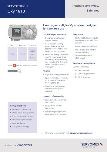 SERVOTOUGH Oxy 1810
9 Pages
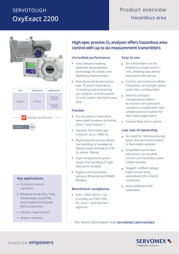 SERVOTOUGH OxyExact 2200
16 Pages
 SERVOPRO 4900 Multigas
10 Pages
 SERVOPRO PureGas
4 Pages
 DF560E Operator Manual
144 Pages
 DF-745 Operator Manual
112 Pages
 SERVOPRO Plasma Operator Manual
78 Pages
 ES 39 Sustainability
11 Pages
 ES 38 Korea Special
19 Pages
 ES 37 Clean Air part II
11 Pages
 ES 36 Purity & Specialty
11 Pages
 ES 35 Photometric Analysis
11 Pages
 ES 34 70th Anniversary
15 Pages
 ES30 Air Separation Units
11 Pages
 ES 29 Clean Air
11 Pages
 ES 28 Gas Analysis Applications
11 Pages
 Sensing Technologies
13 Pages
 DF750 Operator Manual
112 Pages
 DF745SGMax Operator Manual
90 Pages
 DF-740 Operator Manual
87 Pages
 DF-730 Operator Manual
82 Pages
 DF560E Operator Manual 082616
146 Pages
 DF550E Operator Manual 082616
134 Pages








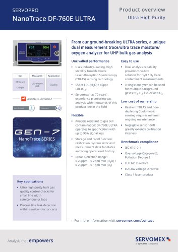
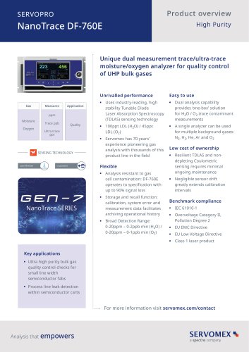


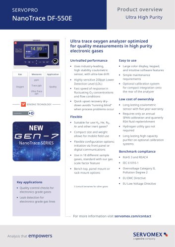


Archived catalogs
 Servomex Product Portfolio
2 Pages
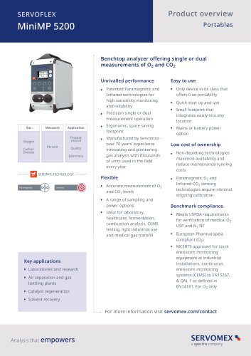 SERVOFLEX MiniMP 5200
7 Pages
 Servomex Product Guide - Issue 8
15 Pages
 Servomex Service Guide - Issue 3
13 Pages
 Servomex Gas Guide - Issue 4
76 Pages
 SERVOPRO HFID
4 Pages
 SERVOPRO NOx
4 Pages
 Servomex Product Guide Issue 7
13 Pages
 Servomex Service Guide Issue 2
11 Pages
 Servomex GAS GUIDE issue 3
77 Pages
 Servomex Service Portfolio
2 Pages
 SERVOTOUGH H2 Scan
2 Pages
 SERVOTOUGH SpectraScan 2400
2 Pages
 Servomex Gas Guide 2022
65 Pages




- SERVOMEX concentration analyzer
- SERVOMEX monitoring analyzer
- Liquids analyzer
- Automatic analyser
- SERVOMEX benchtop analyzer
- Solids analyser
- SERVOMEX process analyzer
- SERVOMEX portable analyzer
- Continuous analyzer
- Real-time analyzer
- SERVOMEX integration analyzer
- Laboratory analyzer
- SERVOMEX compact analyzer
- SERVOMEX digital analyzer
- Infrared analyser
- Calibration analyzer
- Waterproof analyzer
- Temperature analyzer