- Company
- Products
- Catalogs
- News & Trends
- Exhibitions
DF560E Operator Manual
1 /144Pages

DF560E Operator Manual
1 /144Pages
Catalog excerpts

Operator Manual
Open the catalog to page 1
Copyright 2011 by Servomex Corporation No part of this publication may be reproduced, stored in a retrieval system or transmitted in any form, or by any means including electronic, mechanical, photocopying, recording or otherwise without prior written permission of Servomex Corporation. Stablex, Bi-Strata and are trademarks of Servomex Corporation. VCR is a registered trademark of the Cajon Compa
Open the catalog to page 2
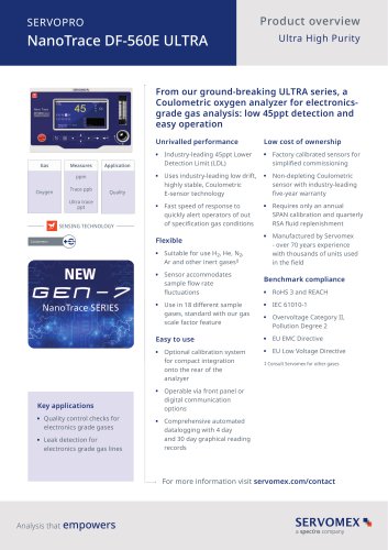
DF-560E Operator Manual Firmware v3.36 Version 062522 Your NanoTrace Oxygen Analyzer has been designed, manufactured and is supported under ISO-9001 controls, thus helping to insure the highest possible standards of quality. Every analyzer that Servomex manufactures is tested and operated on a variety of gas concentrations to insure that it functions properly when you receive it. The certificate of calibration assures your analyzer has been calibrated on gases that are traceable to NIST standards. With proper maintenance, your analyzer should remain calibrated for years. For a fast and successful...
Open the catalog to page 3
Read Me First… Unpacking Procedure Follow the procedure below to unpack your DF-560E Oxygen Analyzer. 1. Examine the condition of the packaging and its contents. If any damage is apparent, immediately notify the carrier and Servomex. Do not proceed with the installation. 2. Check the contents against the packing slip to make sure the shipment is complete. Unattached equipment may be shipped with the analyzer in supplemental packaging. Shortages should be reported to Servomex immediately. 3. All DF-560E analyzers are shipped with the following: Item One bottle of Hummingbird Brand Electrolyte...
Open the catalog to page 4
Unlike much UHP analytical equipment, DF-560E does not require constant maintenance. However the maintenance intervals for zero and span calibrations, as well as electrolyte and purifier maintenance, must be determined and followed carefully. Thank you for selecting the DF-560E Analyzer. Servomex designs, manufactures, exhaustively tests, and supports every analyzer under ISO-9001 control. You should expect every Servomex analyzer to arrive in perfect working order and, with good maintenance, provide years of trouble-free service.
Open the catalog to page 5
2 Cautions There are a number of warnings and cautions that must be observed to avoid damage to the analyzer as well to insure the safety of its users. The analyzer must be operated in a manner specified in this manual. This analyzer is for safe area indoor use only Servomex cannot be responsible for direct or consequential damages that result from installing or operating the analyzer in a manner not described in this manual. Importantly, the analyzer has been designed for use with inert, non-toxic, non-combustible sample gases only. Servomex cannot be responsible for direct or consequential...
Open the catalog to page 13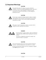
2.2 Important Warnings CAUTION Potentially hazardous AC voltages are present within this instrument. Leave all servicing to qualified personnel. Disconnect the AC power source when installing or removing: external connections, the sensor, the electronics, or when charging or draining electrolyte. CAUTION Do not setup or operate the Oxygen Analyzer without a complete understanding of the instructions in this manual. Do not connect this Analyzer to a power source until all signal and plumbing connections are made. CAUTION This analyzer must be operated in a manner consistent with its intended use...
Open the catalog to page 14
DO NOT SHIP THE ANALYZER WITH ELECTROLYTE IN THE SENSOR – THOROUGHLY DRAIN AND RINSE SENSOR BEFORE SHIPPING EMI DISCLAIMER This Analyzer generates and uses small amounts of radio frequency energy. There is no guarantee that interference to radio or television signals will not occur in a particular installation. If interference is experienced, turn-off the analyzer. If the interference disappears, try one or more of the following methods to correct the problem: • • Move the instrument with respect to the receiver. Reorient the receiving antenna. Place the analyzer and receiver on different AC...
Open the catalog to page 15
3 Specifications Range of Operation: 0-20ppm Lowest Detection Level (LDL): 45 ppt @ Constant Conditions Resolution (Smallest Detectable Change): 22.5 ppt Calibrated Accuracy: ±3 percent of reading or ±0.1 ppb (whichever is greater) @ Constant Conditions Response Time: Typically less than 15 seconds to read 90 percent of a step change. The equilibrium time is dependent on specific conditions. Upset Recovery Time: Typically less than 5 minutes from a high ppm upset to within 10 ppb of the previous stable reading. Ambient Operating Temperature: 0° C to 45° C (32° F to 110° F) Operating Altitude:...
Open the catalog to page 16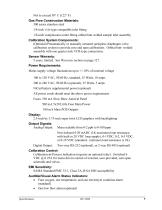
Not to exceed 50° C (122° F) Gas Flow Construction Materials: 300 series stainless steel 1/4-inch VCR-type compatible inlet fitting 1/8-inch compression outlet fitting orbital butt welded sample inlet assembly Calibration System Components: (Optional) Pneumatically or manually actuated springless diaphragm valve calibration system to provide zero and span calibrations. Orbital butt- welded assembly with one quarter inch VCR-type connections. Sensor Warranty: 5 years, limited. See Warranty section on page 127. Power Requirements: Mains supply voltage fluctuations up to +/-10% of nominal voltage...
Open the catalog to page 17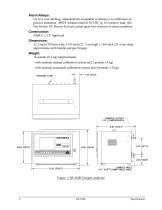
Alarm Relays: Up to 4, non-latching, independently assignable to alarms or to calibration-inprocess indicators. SPDT contacts rated at 30 VDC @ 5A resistive load. (Do Not Switch AC Power) Fail safe action upon loss of power to alarm condition. Construction: NEMA 1, CE Approved Dimensions: 12.2-inch (30.9cm) wide x 8.9-inch (22.7 cm) high x 10.0-inch (25.4 cm) deep approximate (with handle and gas fittings) Weight: 18 pounds (8.2 kg) (approximate) - with optional manual calibration system add 2 pounds (.9 kg) - with optional automated calibration system add 4 pounds (1.8 kg) Figure 1: DF-560E...
Open the catalog to page 18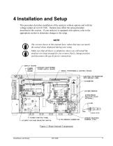
4 Installation and Setup This procedure describes installation of the analyzer without options and with the voltage output set to 0-10 VDC. Options may affect the setup procedure described in this section. If your analyzer is equipped with options, refer to the appropriate section to determine changes to the setup. NOTE The screens shown in this manual have values that may not match the actual values displayed during your setup. Make sure that all floors or platforms where you will install the analyzer are large enough for you to move freely, change position and disconnect the gas & power connections....
Open the catalog to page 19All SERVOMEX catalogs and technical brochures
 Gas Guide Issue 6
74 Pages
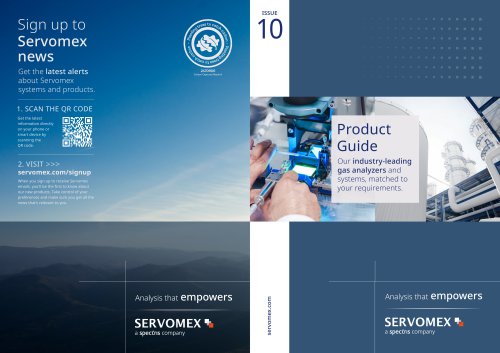 Product Guide Issue 10
14 Pages
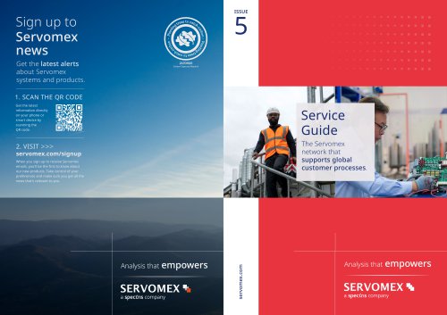 Service Guide Issue 5
12 Pages
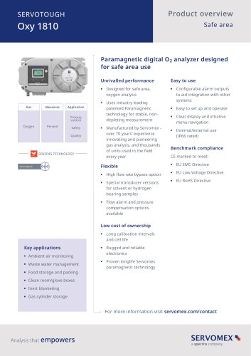 SERVOTOUGH Oxy 1810
9 Pages
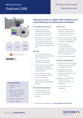 SERVOTOUGH OxyExact 2200
16 Pages
 SERVOPRO 4900 Multigas
10 Pages
 SERVOPRO PureGas
4 Pages
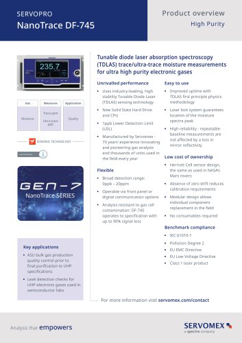
 DF-745 Operator Manual
112 Pages
 ES 39 Sustainability
11 Pages
 ES 38 Korea Special
19 Pages
 ES 37 Clean Air part II
11 Pages
 ES 36 Purity & Specialty
11 Pages
 ES 35 Photometric Analysis
11 Pages
 ES 34 70th Anniversary
15 Pages
 ES30 Air Separation Units
11 Pages
 ES 29 Clean Air
11 Pages
 ES 28 Gas Analysis Applications
11 Pages
 Sensing Technologies
13 Pages
 DF760E Operator Manual
182 Pages
 DF750 Operator Manual
112 Pages
 DF745SGMax Operator Manual
90 Pages
 DF-740 Operator Manual
87 Pages
 DF-730 Operator Manual
82 Pages
 DF560E Operator Manual 082616
146 Pages
 DF550E Operator Manual 082616
134 Pages


Archived catalogs
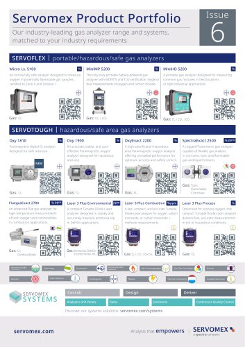
 Servomex Product Portfolio
2 Pages
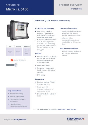
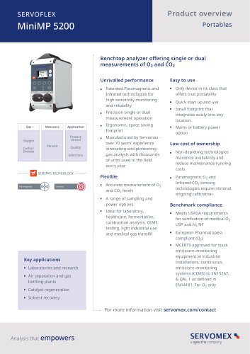 SERVOFLEX MiniMP 5200
7 Pages
 Servomex Product Guide - Issue 8
15 Pages
 Servomex Service Guide - Issue 3
13 Pages
 Servomex Gas Guide - Issue 4
76 Pages
 SERVOPRO HFID
4 Pages
 SERVOPRO NOx
4 Pages
 Servomex Product Guide Issue 7
13 Pages
 Servomex Service Guide Issue 2
11 Pages
 Servomex GAS GUIDE issue 3
77 Pages
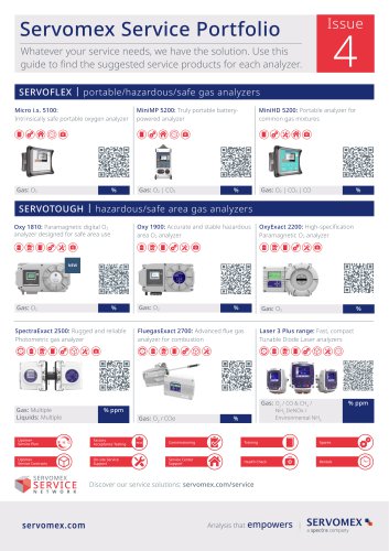
 Servomex Service Portfolio
2 Pages
 SERVOTOUGH H2 Scan
2 Pages
 SERVOTOUGH SpectraScan 2400
2 Pages
 Servomex Gas Guide 2022
65 Pages


- SERVOMEX gas analyzer
- SERVOMEX concentration analyzer
- SERVOMEX monitoring analyzer
- Liquids analyzer
- Automatic analyser
- SERVOMEX benchtop analyzer
- Solids analyser
- SERVOMEX process analyzer
- SERVOMEX portable analyzer
- Continuous analyzer
- SERVOMEX integration analyzer
- Real-time analyzer
- Laboratory analyzer
- SERVOMEX compact analyzer
- SERVOMEX digital analyzer
- Infrared analyser
- Calibration analyzer
- Temperature analyzer
- Waterproof analyzer