TMA series
1 /28Pages

TMA series
1 /28Pages
Catalog excerpts

Linear actuators TMA Series Linear Actuators TMA Series rear attachment with bushes Linear Actuators TMA Series rear attachment with pins Example of system with 2 linear actuators TMA Series and only one electric motor 156
Open the catalog to page 1
Linear actuators TMA Series 5.1 MANUFACTURING FEATURES Housing: designed and manufactured in monobloc form to achieve a compact body able to sustain heavy axial loads and have a high rigidity. Material: grey cast iron EN-GJL-250 (UNI EN 1561) Tapered roller bearings Oil seal Gearbox grease nipple Oil seal Acme screw Acme screw grease nipple 5 Bronze guide Fixing pins Input drive: precision worm gear geometric design for high efficiency, involute profile ZI (UNI 4760 Part 4), low angular backlash. Worm shaft in case hardened steel 20 MnCr 5 (UNI EN 10084), with thread and input shafts ground....
Open the catalog to page 2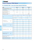
Linear actuators TMA Series 5.2 TECHNICAL DATA - acme screw linear actuators TMA Series SIZE Attachment for IEC standard motor (flange and hollow shaft) Attachment for IEC standard motor (flange adapter + coupling) Load capacity [kN], (push - pull) 1-start acme screw Input solid shaft diameter Starting torque on input shaft at max. load [Nm] Starting efficiency Linear travel [mm] for 1 input shaft revolution Reaction torque on acme screw at max. load [Nm] Mass of actuator without acme screw Mass of each 100 mm of acme screw
Open the catalog to page 3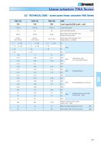
Linear actuators TMA Series 5.2 TECHNICAL DATA - acme screw linear actuators TMA Series TMA 100 Attachment for IEC standard motor (flange and hollow shaft) Attachment for IEC standard motor (flange adapter + coupling) Load capacity [kN], (push - pull) 1-start acme screw Input solid shaft diameter Mass of actuator without acme screw Mass of each 100 mm of acme screw Linear travel [mm] for 1 input shaft revolution Starting efficiency Starting torque on input shaft at max. load [Nm] Reaction torque on acme screw at max. load
Open the catalog to page 4
Linear actuators TMA Series 5.3 PERFORMANCE (actuator WITHOUT input gearbox) ACME SCREW LINEAR ACTUATORS TMA Series with AC 3-PHASE MOTOR PERFORMANCE with: Duty Cycle Fi = 30 % over 10 min at ambient temperature 25 °C LINEAR SPEED [mm/s] MOTOR: POWER [kW] — N° of POLES SPEED [rpm] SELF-LOCKING COEFFICIENT Note: Lower linear speeds are achievable with 3-phase 6-pole electric motors. 1) value limited by electric motor power The total dynamic efficiency (h) of TMA Series actuators without input drive, used to determine the dynamic load is calculated as follows: h = h1 × h2 × h3 where: h1 – wormgear...
Open the catalog to page 5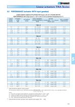
Linear actuators TMA Series 5.3 PERFORMANCE (actuator WITH input gearbox) ACME SCREW LINEAR ACTUATORS TMA Series with AC 3-PHASE MOTOR PERFORMANCE with: Duty Cycle Fi = 30 % over 10 min at ambient temperature 25 °C LINEAR SPEED [mm/s] ACTUATOR: RATIO INPUT GEARBOX: MOTOR: CENTRE DISTANCE POWER [kW] — N° of POLES RATIO SPEED [rpm] SELF-LOCKING COEFFICIENT value limited by electric motor power The total dynamic efficiency (h) of TMA Series actuators with input drive, used to determine the dynamic load is calculated as follows: h = h 1 × h 2 × h3 × h 4 where: h1 – input drive wormgear dynamic efficiency,...
Open the catalog to page 6
Linear actuators TMA Scries Rear attachment: BUSHES Input shaft axis X PERPENDICULAR to the median plane , determined by the rear attachment axis and by the front attachment axis Rear attachment axis between input shaft axis J- and front attachment axis -m4- Rear attachment: PINS Input shaft axis X PERPENDICULAR to the median plane , determined by the rear attachment axis and by the front attachment axis Rear attachment axis between input shaft axis -J- and front attachment axis Rear attachment: BUSHES Input shaft axis J- PARALLEL to rear attachment axis and front attachment axis Rear attachment...
Open the catalog to page 7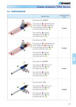
Linear actuators TMA Scries Rear attachment: BUSHES Input shaft axis ■%■ PERPENDICULAR to the median plane , determined by the rear attachment axis and by the front attachment axis -ti^- Input shaft axis J- between rear attachment axis and front attachment axis Rear attachment: PINS Input shaft axis X PERPENDICULAR to the median plane , determined by the rear attachment axis and by the front attachment axis Input shaft axis J- between rear attachment axis and front attachment axis -ift- Rear attachment: BUSHES Input shaft axis J- PARALLEL to rear attachment axis and front attachment axis Input...
Open the catalog to page 8
Linear actuators TMA Scries 5.5 OVERALL DIMENSIONS - actuator WITHOUT input gearbox Input shaft axis perpendicular to front and rear attachments axis Configurations with rear attachment axis-^- between input shaft axis J- and front attachment axis o_ Flange + hollow shaft 0DA \ _ / / Lc - RETRACTED ACTUATOR length La - EXTENDED ACTUATOR length Front attachment HINGED HEAD Rear attachment Rear attachment Front attachment BALL JOINT
Open the catalog to page 9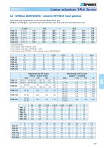
Linear actuators TMA Series 5.5 OVERALL DIMENSIONS - actuator WITHOUT input gearbox Input shaft axis perpendicular to front and rear attachments axis Config.1 and Config.2 - rear attachment axis between input shaft axis and front attachment axis without bellows with bellows and STROKE < 600 3) with bellows and 600 < STROKE < 1200 4) with bellows and STROKE > 1200: please, contact SERVOMECH 2)
Open the catalog to page 10
Linear actuators TMA Scries 5.5 OVERALL DIMENSIONS - actuator WITHOUT input gearbox Input shaft axis parallel to front and rear attachments axis Configurations with rear attachment axis-^- between input shaft axis J- and front attachment axis Lc - RETRACTED ACTUATOR length La - EXTENDED ACTUATOR length A HIIIIII A Hll IIIIA ^^^t"^^\ Front attachment Flange + hollow shaft 0Df | Rear attachment Rear attachment Front attachment BALL JOINT
Open the catalog to page 11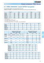
Linear actuators TMA Series 5.5 OVERALL DIMENSIONS - actuator WITHOUT input gearbox Input shaft axis parallel to front and rear attachments axis Config.3 and Config.4 - rear attachment axis between input shaft axis and front attachment axis without bellows with bellows and STROKE < 600 3) with bellows and 600 < STROKE < 1200 4) with bellows and STROKE > 1200: please, contact SERVOMECH 2)
Open the catalog to page 12All SERVOMECH catalogs and technical brochures
 BALL SCREW JACKS
132 Pages
 LINEAR ACTUATORS HSA SERIES
36 Pages
 Ball Screw Jacks
128 Pages
 Bevel gearboxes
52 Pages
 SERVOMECH Linear Actuators
2 Pages
 UBA, UAL series
30 Pages
 CLA, CLB series
24 Pages
 Acme Screw Jacks
100 Pages
 Mechanical Linear Actuators
212 Pages
 Ball screws and nuts catalogue
35 Pages


- SARRALLE electric actuator
- Right angle gearhead
- SARRALLE nut
- Compact gearhead
- Solid-shaft gearhead
- Hollow-shaft gearhead
- SARRALLE metal nut
- SARRALLE compact actuator
- Transmission gearhead
- Screw actuator
- Industrial actuator
- DC actuator
- High-performance gearhead
- Low-noise gearhead
- High-efficiency gearhead
- Bevel gearhead
- Electric motor gearhead
- Modular gearhead