CLA, CLB series
1 /24Pages

CLA, CLB series
1 /24Pages
Catalog excerpts

Linear actuators CLA Series and CLB Series CLA-CLB Series, size 30 - 40 3 CLA-CLB Series, size 50
Open the catalog to page 1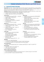
Linear actuators CLA Series and CLB Series 3.1 MANUFACTURING FEATURES Input drive: worm gear - precision helical wheel, geometric design for high performance, involute profile ZI (UNI 4760 : Part 4), low angular backlash. Worm in case hardened steel 20 MnCr 5 (UNI EN 10084), with thread and input shafts ground. Helical wormwheel in bronze EN 1982 – CuSn12-C. Housing: designed and manufactured in monobloc form to obtain a compact body able to sustain heavy axial loads and high machining accuracy. High quality materials are used: ▪ castings in aluminium alloy EN 1706 AC-AlSi6Cu4 ▪ castings in grey...
Open the catalog to page 2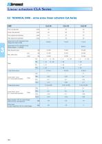
Linear actuators CLA Series 3.2 TECHNICAL DATA - acme screw linear actuators CLA Series SIZE Outer tube diameter Front attachment diameter Rear attachment diameter Attachment for IEC standard motor (flange and hollow shaft) Attachment for IEC standard motor (flange adapter + coupling) Max. dynamic load Max. static load Linear travel [mm] for 1 input shaft revolution 2-start acme screw RV2 Ratio Linear travel [mm] for 1 input shaft revolution Mass (actuator 100 mm stroke length, without motor, with lubricant) Extra-mass for each additional 100 mm stroke length
Open the catalog to page 3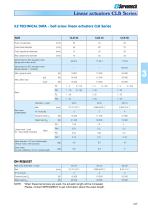
Linear actuators CLB Series 3.2 TECHNICAL DATA - ball screw linear actuators CLB Series SIZE Outer tube diameter Front attachment diameter Rear attachment diameter Attachment for IEC standard motor (flange and hollow shaft) Attachment for IEC standard motor (flange adapter + coupling) Max. dynamic load Max. static load Diameter × Lead Ball Ball screw (STANDARD) Linear travel [mm] for 1 input shaft revolution Mass (actuator 100 mm stroke length, without motor, with lubricant) Extra-mass for each additional 100 mm stroke length ON REQUEST Ball screw (Diameter × Lead) Ball When these ball screws...
Open the catalog to page 4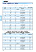
Linear actuators CLA Series ACME SCREW LINEAR ACTUATORS CLA Series with AC 3-PHASE MOTOR PERFORMANCE with: Duty Cycle Fi = 30 % over 10 min at ambient temperature 25 °C LINEAR SPEED [mm/s] MOTOR: POWER [kW] — N° of POLES SPEED [rpm] SELF-LOCKING COEFFICIENT ACME SCREW LINEAR ACTUATORS CLA Series with AC 1-PHASE MOTOR PERFORMANCE with: Duty Cycle Fi = 30 % over 10 min at ambient temperature 25 °C LINEAR SPEED [mm/s] MOTOR: POWER [kW] — N° of POLES SPEED [rpm] SELF-LOCKING COEFFICIENT
Open the catalog to page 5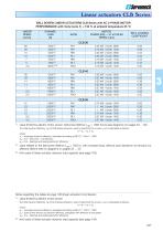
Linear actuators CLB Series BALL SCREW LINEAR ACTUATORS CLB Series with AC 3-PHASE MOTOR PERFORMANCE with: Duty Cycle Fi = 100 % at ambient temperature 25 °C LINEAR SPEED [mm/s] MOTOR: POWER [kW] — N° of POLES SPEED [rpm] SELF-LOCKING COEFFICIENT value limited by electric motor power; ball screw lifetime L10h > 1000 hours (see diagrams on pages 34 ... 35) The total dynamic efficiency (h) of CLB Series actuators, used to determine the dynamic load is calculated as follows: h = h 1 × h2 × h 3 where: h1 – wormgear dynamic efficiency, calculated according to BS 721 : Part 2 : 1983 h2 = 0.9 – ball...
Open the catalog to page 6
Linear actuators CLA Series 3.4 OVERALL DIMENSIONS ACME SCREW LINEAR ACTUATORS CLA Series, size 30 — 40 AC 3-phase or 1-phase MOTOR La = Lc + STROKE Lc = S + STROKE T + STROKE Stroke end switch cover ACME SCREW GREASE NIPPLE PIN FRONT ATTACHMENTS WITH BRAKE STANDARD HEAD with threaded bore BA Lc - RETRACTED actuator length La - EXTENDED actuator length
Open the catalog to page 7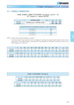
Linear actuators CLA Series 3.4 OVERALL DIMENSIONS ACME SCREW LINEAR ACTUATORS CLA Series, size 30 — 40 AC 3-phase or 1-phase MOTOR STROKE CODE STROKE [mm] = STROKE CODE ACTUATOR with FC in STANDARD execution NOTE: Greater stroke lengths available on request. For stroke lengths longer than 800 mm it is necessary to increase the guided length between push rod and outer tube to avoid axial backlash. Dimensions S, T and Q shall be considered increased by 200 mm for stroke lengths up to 1500 mm. FRONT ATTACHMENT Dimensions a 65 80
Open the catalog to page 8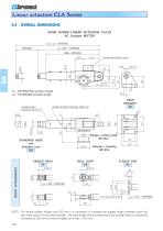
Linear actuators CLA Series 3.4 OVERALL DIMENSIONS ACME SCREW LINEAR ACTUATOR CLA 50 AC 3-phase MOTOR La = Lc + STROKE STROKE Lc = 367 + STROKE 288 + STROKE Stroke end switch cover 3 Lc - RETRACTED actuator length La - EXTENDED actuator length GUIDE BUSH GREASE NIPPLES ACME SCREW GREASE NIPPLES STANDARD HEAD with threaded bore BA HINGED HEAD TF FRONT ATTACHMENTS Flange + hollow shaft IEC B14 Adapter + coupling IEC B14 NOTE: For stroke lengths longer than 800 mm it is necessary to increase the guided length between push rod and outer tube to avoid axial backlash. The tube length and the dimensions...
Open the catalog to page 9
Linear actuators CLB Series 3.4 OVERALL DIMENSIONS BALL SCREW LINEAR ACTUATOR CLB 50 AC 3-phase MOTOR La = Lc + STROKE STROKE Lc = 446 + STROKE 372 + STROKE Stroke end switch cover 3 Lc - RETRACTED actuator length La - EXTENDED actuator length GUIDE BUSH GREASE NIPPLES ACME SCREW GREASE NIPPLES Flange + hollow shaft IEC B14 STANDARD HEAD with threaded bore BA HINGED HEAD TF FRONT ATTACHMENTS NOTE: For stroke lengths longer than 800 mm it is necessary to increase the guided length between push rod and outer tube to avoid axial backlash. The tube length and the dimensions Lc and La shall be considered...
Open the catalog to page 10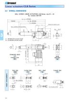
Linear actuators CLB Series 3.4 OVERALL DIMENSIONS BALL SCREW LINEAR ACTUATORS CLB Series, size 30 — 40 AC 3-phase MOTOR La = Lc + STROKE Lc = S + STROKE T + STROKE Stroke end switch cover BALL SCREW GREASE NIPPLE PIN FRONT ATTACHMENTS WITH BRAKE STANDARD HEAD with threaded bore BA Lc - RETRACTED actuator length La - EXTENDED actuator length
Open the catalog to page 11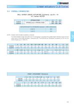
Linear actuators CLB Series 3.4 OVERALL DIMENSIONS BALL SCREW LINEAR ACTUATORS CLB Series, size 30 — 40 AC 3-phase MOTOR STROKE CODE STROKE [mm] = STROKE CODE ACTUATOR with FC in STANDARD execution NOTE: Greater stroke lengths available on request. For stroke lengths longer than 800 mm it is necessary to increase the guided length between push rod and outer tube to avoid axial backlash. Dimensions S, T and Q shall be considered increased by 200 mm for stroke lengths up to 1500 mm. FRONT ATTACHMENT Dimensions a 65 80
Open the catalog to page 12All SERVOMECH catalogs and technical brochures
 BALL SCREW JACKS
132 Pages
 LINEAR ACTUATORS HSA SERIES
36 Pages
 Ball Screw Jacks
128 Pages
 Bevel gearboxes
52 Pages
 SERVOMECH Linear Actuators
2 Pages
 TMA series
28 Pages
 UBA, UAL series
30 Pages
 Acme Screw Jacks
100 Pages
 Mechanical Linear Actuators
212 Pages
 Ball screws and nuts catalogue
35 Pages


- Electric actuator
- Right angle gearhead
- Nut
- Compact gearhead
- Solid-shaft gearhead
- Hollow-shaft gearhead
- Metal nut
- Compact actuator
- Transmission gearhead
- Screw actuator
- Industrial actuator
- DC actuator
- High-performance gearhead
- Low-noise gearhead
- High-efficiency gearhead
- Bevel gearhead
- Electric motor gearhead
- Modular gearhead