Ball screws and nuts catalogue
1 /35Pages

Ball screws and nuts catalogue
1 /35Pages
Catalog excerpts
BALL SCREWS AND NUTS INDEX 1. DESIGN 1.1 Introduction . . . . . . . . . . . . . . . . . . . . . . . . . . . . . . . . . . . . . . . . . . . . . . . . . . . . . . . . . . . . . . . . . . . 1.2 Ball track prole . . . . . . . . . . . . . . . . . . . . . . . . . . . . . . . . . . . . . . . . . . . . . . . . . . . . . . . . . . . . . . 1.3 Ball recirculating . . . . . . . . . . . . . . . . . . . . . . . . . . . . . . . . . . . . . . . . . . . . . . . . . . . . . . . . . . . . . 1.4 Backlash or preload . . . . . . . . . . . . . . . . . . . . . . . . . . . . . . . . . . . . . . . . . . . . . . . . ....
Open the catalog to page 2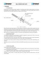
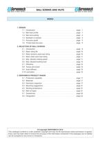
BALL SCREWS AND NUTS 1. DESIGN 1.1 Introduction A ball screw is a mechanical system capable of converting rotary motion to linear motion or vice versa. An example of such a system, shown in Figure 1, is composed of a ball screw threaded shaft, a ball nut body, balls, ball recirculation elements and wipers (when present). BALL RECIRCULATION ELEMENT BALL NUT BODY BALL SCREW SHAFT BALLS WIPER WIPER Fig. 1 - Ball screw assembly One of the main ball screw features is a high efciency obtained by rolling of balls between the screw shaft and the nut body. Where ball contacts shaft and nut body, the rolling...
Open the catalog to page 3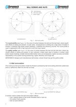
BALL SCREWS AND NUTS Rs = Dw 2 Dw - ball diameter Rs - ball track radius α - contact angle Rs < Dw 2 Dw Dw R Rs s Rs α a) round groove α b) gothic groove Fig. 2 - Ball track prole The round prole (see Figure 2.a): the zone of contact between the ball and the ball track, where signicant effects of sliding are present, is quite wide; consequences of sliding are a high wear of bodies in contact, a relatively high power losses (heating), a relatively low efciency and life. The round prole is used in applications with a high load and a very low linear speed. The gothic prole (see Figure 2.b): the...
Open the catalog to page 4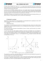
BALL SCREWS AND NUTS A solution with the RADIAL liner (see Figure 3.a) is usually used in ball screws with lead not greater then 20 mm; the liner is t in the groove present in the ball nut body and restricts a ball trajectory at one single revolution around the ball screw shaft. A solution with the FRONTAL deector (see Figure 3.b) is usually used in ball screws with lead greater then 10 mm and in all multiple-start ball screws. The recirculation of balls is obtained by deectors tted on ends of the ball nut body and joined with an axial hole (passing through the body); the deectors deviate ball...
Open the catalog to page 5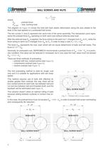
BALL SCREWS AND NUTS Fpr where: Fpr Fax max Fax max 2.83 - preload force - max. working load The diagram on Figure 4.b shows the total ball track elastic deformation along the axis related to the level of the load applied on a preloaded ball screw. The two curves (1 and 2) represent two semi-nuts of the same assembly. The intersection point represents the preload force Fpr operating on both semi-nuts without external axial load. After the external load Fax is applied, the force acting to the semi-nut 1 changes from Fpr to F1, while the force acting to semi-nut 2 changes from Fpr to F2, in order...
Open the catalog to page 6
BALL SCREWS AND NUTS The second and the third preloading method can applied either to ball screws with single nut or to ball screws with double nut, giving them an optimal efciency. There are only two contact points for each ball, one between ball and nut and one between ball and threaded shaft, so a sliding between surfaces in contact may not occur. In case of ball screws with single nut, the preload force is obtained by thread lead variation (called shift) during the nishing of the internal thread. In case of ball screws with double preloaded nut - compression preload, the contact points have...
Open the catalog to page 7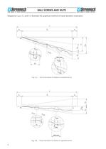
BALL SCREWS AND NUTS Diagrams Figure 8.a and 8.b illustrate the graphical method of travel deviation evaluation. l lu le le 0 e 0a ep C l0 V2πa ep Vup 300 mm V2πp V300p 2π V300a Fig. 8.a - Travel deviation in relation to nominal travel l lu le ls V2πa V2πp V300a 2π V300p 300 mm Fig. 8.b - Travel deviation in relation to specied travel 6 ep 0 e sa ep le
Open the catalog to page 8
BALL SCREWS AND NUTS 2. SELECTION OF BALL SCREWS 2.1 Introduction Elements that affect the functioning of the ball screw, as well as guidelines for proper sizing of ball screws, are indicated below. In order to allow correct sizing of ball screws, the following points must be known: ▪ required life, ▪ detailed working cycle (all load levels, relative speed and working period of time), ▪ mounting conditions, ▪ environmental conditions, ▪ lubrication conditions. During work, the load applied to the ball screw must be coaxial with a screw itself. It is essential for proper functioning of the ball...
Open the catalog to page 10
BALL SCREWS AND NUTS ▪ case 2: variable axial load at constant speed Fm t1 F13 3 t1 t2 t3 ... t2 F23 t1 t2 t3 ... t3 F33 t1 t2 t3 ... ... where: F1, F2, F3, ... - level of axial load, relative to a single subcycle t1, t2, t3, ... - time period of a single subcycle F [N] F1 = 10 000 example: i ti [s] Fi [N] 1 2 3 25 40 35 10 000 5 000 2 500 Fm = 6 735 Fm [N] 6 735 F2 = 5 000 F3 = 2 500 0 ▪ 25 65 100 t [s] n3 nm t3 ... case 3: variable axial load at variable speed Fm n1 nm F13 3 t1 F23 t1 t2 t3 ... n2 nm t2 F33 t1 t2 t3 ... t1 t2 t3 ... where: nm n1 t1 t2 n2 t1 t2 t3 ... t1 t2 t3 ... n3 t3 ......
Open the catalog to page 11
BALL SCREWS AND NUTS 2.2 Basic rating life The basic rating life is expressed as a number of revolutions of the threaded shaft with respect to the nut or vice versa, before fatigue effects and consequences occur on the threaded shaft and/or nut and/or rolling bodies. The following formula is used for calculation of the basic rating life (L10): L10 3 Ca Fm 106 f sh where: L10 [rev] - basic rating life of the ball screw - basic dynamic axial load rating Ca [N] Fm [N] - equivalent axial dynamic load - shock factor fsh fsh = 1: load without shocks 1 < fsh 1.3: load with light shocks 1.3 < fsh 1.8:...
Open the catalog to page 12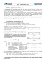
BALL SCREWS AND NUTS 2.4 Basic static axial load rating (C0a) The basic static axial load rating (C0a) is a static load, applied axially and centrically to the ball screw, which generates a total permanent deformation of ball and ball track, at the most heavily point of contact between them, of 0.0001 × Dw (Dw - ball diameter). In applications where the load is applied to a stationary ball screw or a ball screw rotating at very low speed (less then 10 rpm) for short duration, the basic static axial load rating (C0a) should be greater then the load applied, in order to guaranty a proper working...
Open the catalog to page 13All SERVOMECH catalogs and technical brochures
 BALL SCREW JACKS
132 Pages
 LINEAR ACTUATORS HSA SERIES
36 Pages
 Ball Screw Jacks
128 Pages
 Bevel gearboxes
52 Pages
 SERVOMECH Linear Actuators
2 Pages
 TMA series
28 Pages
 UBA, UAL series
30 Pages
 CLA, CLB series
24 Pages
 Acme Screw Jacks
100 Pages
 Mechanical Linear Actuators
212 Pages


- Actuator
- Linear actuator
- Electric actuator
- Right angle gearhead
- Compact gearhead
- Solid-shaft gearhead
- Hollow-shaft gearhead
- Metal nut
- Compact actuator
- Transmission gearhead
- Screw actuator
- Industrial actuator
- DC actuator
- High-performance gearhead
- Low-noise gearhead
- High-efficiency gearhead
- Bevel gearhead
- Electric motor gearhead
- Modular gearhead