
- Catalogs
- Servo-Matik
- SERVO-INV


SERVO-INV
SERVO-INV
This section stresses the importance of adhering to the manual's instructions to prevent inverter damage. It specifies that only authorized personnel should manage start-up and maintenance due to safety concerns.
Warnings are provided about electric shock risks and the necessity of grounding the device. Users are advised against opening the device and reminded to use specified cable sizes and fuses to minimize fire risks.
Common errors include incorrect cable connections, changing fuse rates, and operating the device outside specified environmental conditions, which can void the warranty.
Placing: The device should be placed in a well-ventilated, dry, and non-corrosive environment, with at least 50 cm of free space around it.
Transportation: Transport the device upright with protective packaging intact.
Unpacking: Inspect for damage and ensure all components are intact before installation.
Instructions emphasize safe electrical connections, proper grounding, and using correct cable dimensions as specified in the manual.
Detailed steps for starting and shutting down the inverter are outlined, including the sequence of turning on switches and breakers.
The main menu interface on the LCD screen is described, including buttons for navigating functions and monitoring system status.
Feeding from Battery: Operates on battery power until fully discharged.
Static Bypass Mode: Automatically switches to bypass line during overload or inverter issues, but does not protect against mains voltage irregularities.
Manual By-Pass Mode: Used for maintenance, allowing the load to be fed directly from mains voltage.
Maintenance should only be performed by trained personnel. The manufacturer is not responsible for damages due to user errors or misuse. Device covers should only be opened for maintenance or repair by competent individuals.
The device is designed with life-critical parts, and all necessary precautions have been taken to ensure safety. Users must be knowledgeable about the device and avoid touching dangerous parts, especially when covers are open. The device's lifetime is specified as 5 years according to the regulation dated 13/6/2014.
Periodic maintenance is not required if the device operates in suitable conditions, but biennial maintenance is recommended. Only authorized personnel should perform maintenance. Users should follow troubleshooting steps before contacting technical service, ensuring all connections and fuses are intact and the device is powered on.
Common issues include 'Overtemperature Close', 'DC High', 'Inverter error', 'Front Panel not energized', and 'DC Low' warnings. Each issue has specific diagnostic steps and solutions, such as checking air holes, calibrating DC Bus voltage, and inspecting connections and components.
The warranty period begins on the invoice date and varies for international markets. It does not cover misuse, unauthorized service, or operation outside specified conditions. SERVOMATIK may replace parts with refurbished ones, and replacement does not extend the warranty period. On-site warranty service is available under certain conditions, with travel costs covered by the customer if no local service center exists.
Catalog excerpts
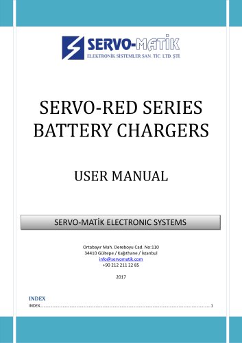
SERVO-INV USER MANUAL SERVO-INV USER‘S MANUAL SERVO-MATİK ELECTRONICS SYSTEMS ORTABAYIR MAH. DEREBOYU CAD. NO:110 34410 GÜLTEPE / KAĞITHANE / İSTANBUL [email protected] +90 212 211 22 85 2017
Open the catalog to page 1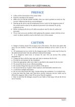
SERVO-INV USER MANUAL • Follow all the instructions in the correct order. • Read the warnings in the manual. • Make sure you read the manual carefully when you want to perform an action on the inverter. Otherwise the device can be damaged. • Starting-up the device and all maintenance/service works for the dangerous parts of the system must be done by the authorized personnel who educated for giving technical service. • Before starting-up the device all safety precautions must be done by authorized personnel. • If you come across any problem while applying this manual, contact with the service...
Open the catalog to page 3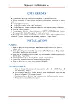
SERVO-INV USER MANUAL • Connection of abnormal loads that excedeeds device nominal power rate, • Wrong connection of input, output and battery cables(phase connection to battery etc.), • Changing phase sequence, • Changing fuse rates of input, output and battery, • Changing batteries, reverse connection of batteries and changing number of batteries, • Working without batteries, • Changing place of device without information of SERVO-MATiK Electronic Systems • Being exposed to physical damage to Device or gotten harm • Being kept out of normal environmental conditions or worked of device.(Temperature,...
Open the catalog to page 4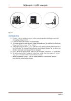
1. Contact with the technical service before using the product and the product with damaged packing material. 2. Carefully unpack the device, avoid damaging. 3. To move the device on its wheels, change the position of the stabiliser to clockwise that placed bottom corner of the wheels. 4. After unpacking the device, check if the device is damaged during transportation or not. To do this, W-Automat, Pacco Breaker and Compact Breaker on the device are checked and make sure the panel is not damaged. 5. Check the device physically to make sure the electrical connections are not broken. 6. Do not...
Open the catalog to page 5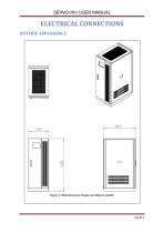
SERVO-INV USER MANUAL Figure 2: Dimensions(can change according to model!)
Open the catalog to page 6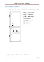
SERVO-INV USER MANUAL FRONT SIDE OF THE DEVICE When you open the front door of the device you can see panels that include BREAKERS, boards and connectors. A: Place of Electronic boards B: Place of Power Breakers C: Place of Cable Terminals 1: Power On Switch 2: Charge/Soft Start Switch 3: Battery Breaker 4: Output Breaker Drawings and specifications can be changed without information.
Open the catalog to page 7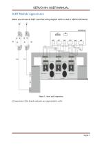
SERVO-INV USER MANUAL IGBT Module Appearance Below you can see all IGBT’s and their wiring diagram which is used in SERVO-INVdevice Figure 1 : Parts and Connections (Connections of the boards and parts are representative only)
Open the catalog to page 8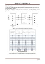
Making Connections ! Cable sizes, breakers and fuses that will be used in the distribution panel must be selected according to device’s power. ! Cable sizes and breakers current shown in the below table. For safety operation, use the given values. Figure 3 : Cable Dimensions Cable dimensions calculated according to current capacity in the tubes!
Open the catalog to page 9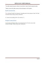
SERVO-INV USER MANUAL ! Use taller cables than given values to move device in case of service operation easily. ! Before connect the cables make sure that all breakers in OFF position. Earth Connection ! For a Safe and Trouble Free Operation, Grounding must be done properly. Make The Earth Connection before doing any other connections. Connect the grounding cable to the terminal ( T ). Output Connections Connect Input and Output Cables to the terminals (R), (S), (T) in the correct order. Connect the Output Neutral Cable to the Terminal (N).
Open the catalog to page 10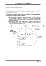
! When connecting the battery cables to terminals, pay attention to polarizations and battery zero voltage point otherwise device will be damaged. • 60 pieces battery connects serial, while placing batteries into battery cabinet or device. After that 1st battery’s (+) point connects to “BATTERY(+)” terminal, 60th battery’s (-) point connects to “BATTERY(-)” terminal and 30th battery’s (+) point connects to “0” terminal. • When using 60 pieces battery and if there is an external battery cabinet for 60 pieces battery, connect (+), 0, (-) points of external battery cabinet with the same name on...
Open the catalog to page 11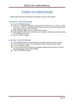
SERVO-INV USER MANUAL ! Before open the device all breakers and switches must be in OFF position. 1) Turn on POWER ON switch. 2) If there is a CHARGE SWITCH or COLD START SWITCH turn it on. After 25s later turn it OFF. If there is a CHARGE BUTTON press it for 25s. At the same time see DC BUS voltage is rising on the LCD Panel. 3) When DC BUS voltage rose, turn on BATTERY breaker. 4) Press ON/OFF button on the LCD Panel for 3 seconds. Check the Lcd Panel and see the INVERTER is working. 5) Turn on OUTPUT breaker. 1) Press ON/OFF button on the Lcd Panel for 3 seconds. See the inverter is closed....
Open the catalog to page 12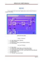
SERVO-INV USER MANUAL You can see the main screen below. Slightly press to icons on the LCD Screen to navigate in the menus. Breaker’s Definitions • S1: Static Bypass Breaker (Optional) • S3: Maintenance ( Manual ) Bypass Breaker (Optional) • A2: Battery Block / Battery Status and Indicator Menu Button • A3: Inverter Status and Indicator Block / Inverter Menu Button • A4: Static Bypass Indicator and Block / Static Bypass Menu Button(Optional) • A5: System Menu Button • A7: Warnings / Events Menu Button
Open the catalog to page 13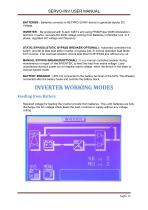
SERVO-INV USER MANUAL BATTERIES : Batteries connects to NETPRO-33-INV device to generate bipolar DC Voltage. INVERTER : Be produced with hi-tech IGBT’s and using PWM(Pulse Width Modulation) technics. Inverter, converts DC BUS voltage coming from Batteries or Rectifier Unit to 3 phase, regulated AC voltage and frequency STATIC BYPASS (STATIC BYPASS BREAKER-OPTIONAL) : Automatic controlled this switch provide to feed load either inverter or bypass line. In normal operation load feeds from inverter. If an overload situation occurs load direct to BYPASS line without any cut. MANUAL BYPASS BREAKER(OPTIONAL)...
Open the catalog to page 14All Servo-Matik catalogs and technical brochures
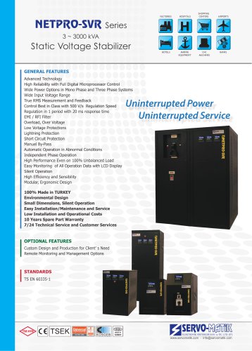 Static Voltaqe Stabilizer
2 Pages
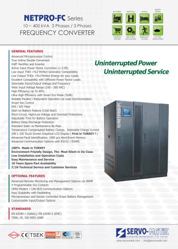 FREQUENCY CONVERTER
2 Pages
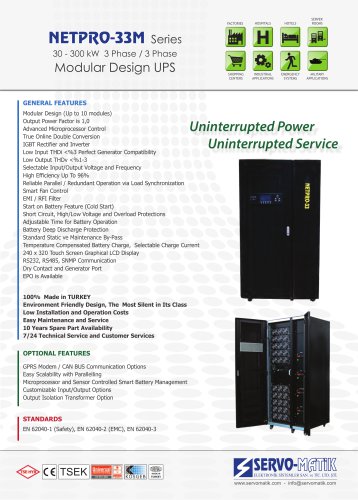 Modular Design UPS
2 Pages
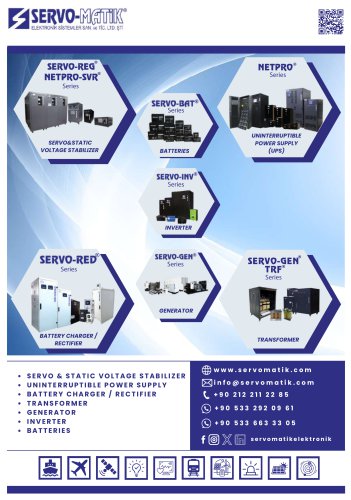 Servo-Matik Catalog
16 Pages
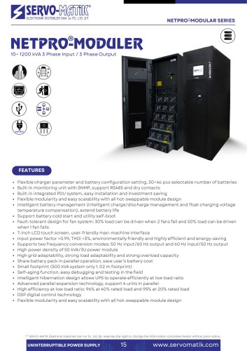 NETPRO MODULER
4 Pages
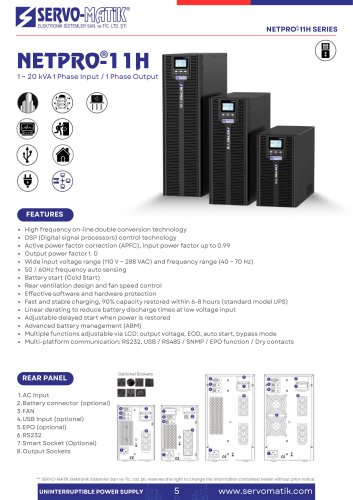 NETPRO-11H
2 Pages
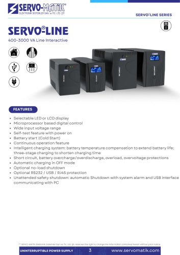 SERVO-LINE
2 Pages
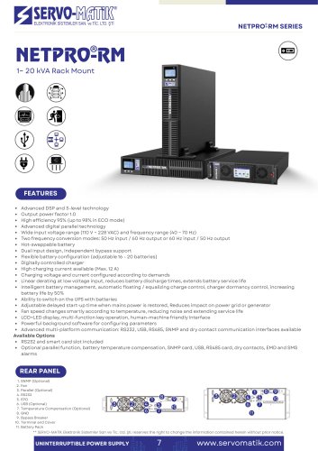 NETPRO-RM
2 Pages
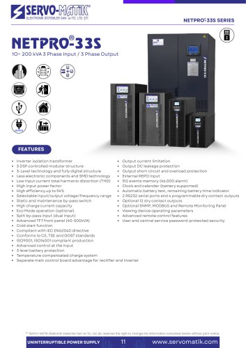 NETPRO-33S
2 Pages
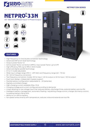 NETPRO-33N
2 Pages
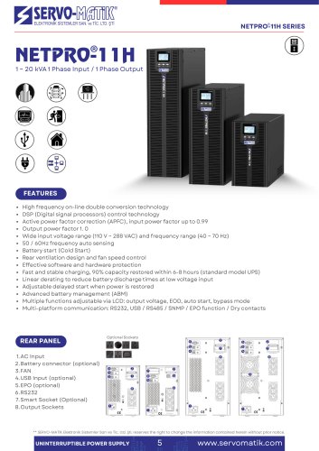 NETPRO-11H
2 Pages
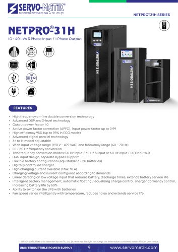 NETPRO-31H
2 Pages
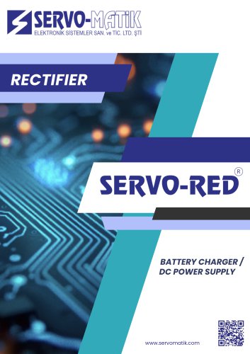 SERVO- RED
11 Pages
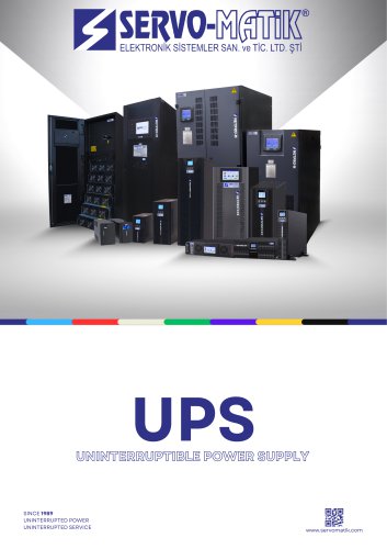 UPS UNINTERRUPTIBLE POWER SUPPLY
23 Pages
- Transformer
- Dry transformer
- Single-phase transformer
- Industrial transformer
- On-line UPS
- Isolation transformer
- Three-phase transformer
- Industrial UPS
- AC buffered power supply
- Single-phase UPS
- Floor-standing transformer
- Three-phase UPS
- UPS with LCD display
- Data center UPS
- Network UPS
- Compact UPS
- AC voltage stabilizer
- Eco mode UPS
- Current rectifier
- Automatic voltage stabilizer