- Catalogs
- SENSORLINK
- Ohmstik PLUS
Ohmstik PLUS
1 /20Pages
Ohmstik PLUS
1 /20Pages
Catalog excerpts

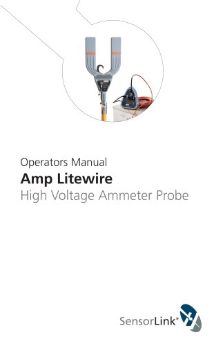
Operators Manual Ohmstik PLUS Multiple Reading Live-Line Micro Ohmmeter
Open the catalog to page 1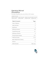
Table of Contents Page Ohmstik Evaluation Method 9-11 Battery Replacement & Cleaning 15 Quality Assurance Back Cover
Open the catalog to page 3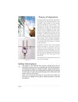
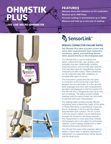
The Ohmstik Plus Live-Line Micro Ohmmeter is designed to be attached directly to an energized, high voltage line and directly read the resistance in micro-ohms. The Ohmstik Plus can be used on almost any connection in a utility. Line splices can be checked after installation, or after many years of service. Bolted terminals, taps, jumpers and substation bus bars can be evaluated. Switches, fused disconnect and normally open switches that have been open for long periods can be measured just after closing. Each of these connections can be measured quickly after installation, or surveyed after long...
Open the catalog to page 4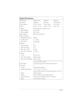
Model Number Sensor Type Sensor Opening Weight 8-082 XT Plus Standard 2.5 in, 6.35 cm 2.4 lbs, 1.10 kg 8-084 Plus Wide Jaw 3.86 in, 9.8 cm 4.0 lbs, 1.81 kg 8-090 Plus Ultra Wide Jaw 6 in 15.4 cm 5 lbs, 2.3 kg Frequency 50Hz Calibrated 60Hz Calibrated Type of Reading Range of Operation Voltage phase to phase True RMS Amps Micro-Ohms Resolution Amps 0.9-99.9A Amps 100-1400A Micro-Ohms 1-999 Micro-Ohms 1000-2500 Accuracy Current Micro-Ohms Absolute Micro-Ohms Repeatability EEC Standards Mechanical Controls Operating Temperature Hotstick Mounting Battery Actual frequency indicated on unit 47 to 53Hz...
Open the catalog to page 5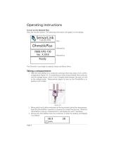
Operating Instructions To turn on the Ohmstik Plus: Press the function button. The following information will appear on the display: SensorLink Copyright 2004 OhmstikPlus F808-XPO-100 Ver. X.XXX Ready The Ohmstik is now ready to measure Amps and Micro-Ohms. Taking a measuerment: 1 Place the OhmstikPlus on a conductor carrying at least two amps of AC current, as depicted in Figure 3.0. It is essential you make contact between the conductor and the voltage sensor, which is the V-shaped plate between the jaws, as well as the voltage probe. Measurement begins as soon as the OhmstikPlus is in position...
Open the catalog to page 6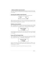
Taking multiple measurements: To take up to eight more readings, simply follow steps one through three over again. The number in the box in the lower left side of the display will indicate which reading you are taking. Viewing the multiple measurements: Press and hold the control switch down until you see the following screen: When the switch is held down, the cursor will continuously scroll through the menu options at the bottom of the screen. To view any of the readings, release the switch when that option is highlighted with the cursor. Deleting measurements: Press and hold the control switch...
Open the catalog to page 7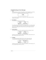
Troubleshooting an Error Message: 1. FULL The OhmstikPlus has room to accomodate nine sets of readings in its memory. Attempting to store additional readings results in the following screen: Full You must clear the data with the “CLEAR DATA” option before any further readings may be taken. 2. NO CONTACT The OhmstikPlus reads current but not µs: This indicates that either one of the two voltage sensors is not making contact. Use the rough edges of the probes to clean the corrosion from the conductor and re-take the measurement. Make certain that both voltage sensors are making contact. 3. POOR...
Open the catalog to page 8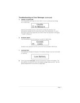
Troubleshooting an Error Message: (continued) 5. UNABLE TO MEASURE The OhmstikPlus uses logic to know when it is on a conductor by looking for a stable load: Hold the OhmstikPlus firmly on the line for at least five seconds. The OhmstikPlus samples the line three times every 100 milliseconds. If it can’t find three consecutive reads that are similar within five seconds it will display “Unable To Measure”. 6. EXCEEDS LIMITS The OhmstikPlus limits the maximum current to 1400 Amps. Exceeds Limits Exceeds Limits indicates that the current limit has exceeded 1400 Amps. 7. LOW BATTERY The following...
Open the catalog to page 9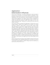
Application: Deterioration Influences Time is not an “aging factor” for fittings. Deterioration is due to increases in resistance of the connection. The increased resistance is produced, in part, by peaks of load and fault current that can heat the interface, even if only temporarily, or for a few cycles (also in part by oxidation of the interfaces during thermal expansion and cooling, and by corrosion accelerated by moisture and chemicals in very small quantities that get in between the strands). Every splice has at least one “uphill” side for water, etc. to run. The reasons we hear that fewer...
Open the catalog to page 10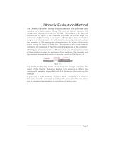
Ohmstik Evaluation Method The Ohmstik Evaluation Method provides definitive and actionable early warnings of a deteriorating fitting. This method directly measures the resistance of the connection with an Ohmstik. The resistance is the electrical condition of the splice. If the resistance is outside the normal range, the connection is deteriorating. A connection with resistance above the normal range is in a failure process, where the time to failure depends on how high the resistance is. The appropriate planned actions for ranges of resistance above normal are shown in Table One. The resistance...
Open the catalog to page 11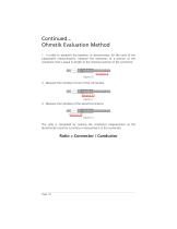
Continued... Ohmstik Evaluation Method 1. In order to establish the baseline, or denominator, for the ratio of the subsequent measurements, measure the resistance of a portion of the conductor that is equal in length to the interface portion of the connector. 2. Measure the interface of one of the connectors. 3. Measure the interface of the second connector. The ratio is calculated by making the conductor measurement as the denominator and the Connector measurement as the numerator. Ratio = Connector / Conductor
Open the catalog to page 12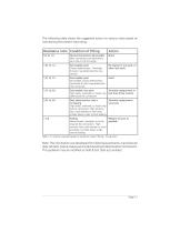
Table 1.0: Actions required based on resistance ratios (fitting / Rconductor)
Open the catalog to page 13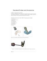
Standard Probes and Accessories 7-081 XT Standard Fused Probe The probe is designed for use in close proximity to adjacent phases or ground structures (see Cautions on page one). In the event of making a phase to phase or phase to ground connection, the Fused Probe will break the connection. Standard Accessories in the 7-081 XT Accessory Kit Include: (1) Fused Probe (1) Contactor Attachment (1) Probe Hook (1) 4" Rod, Straight (1) 4" Rod, Bent (1) Philips Head Screw (1) Coupling Nut (4) Lock Washers (6) Hexnuts Figure 6.0: Fused Probe Configuration with Contactor Attachment Figure 6.1: Fused Probe...
Open the catalog to page 14All SENSORLINK catalogs and technical brochures
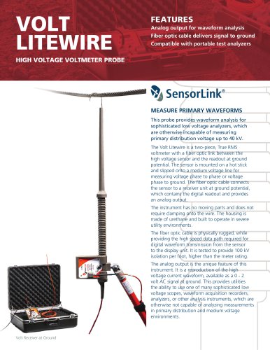 VOLT LITEWIRE
2 Pages
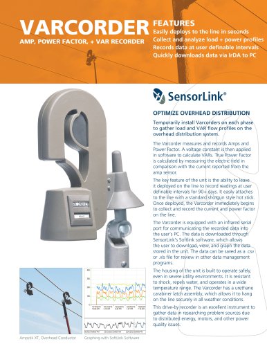 VARCORDER
2 Pages
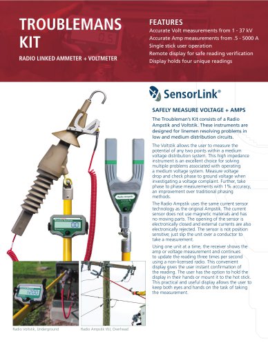 TROUBLEMANS KIT
2 Pages
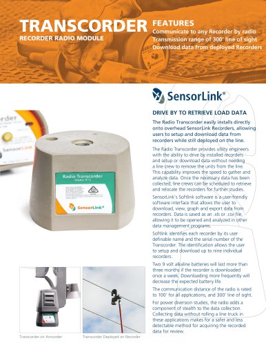 TRANSCORDER
2 Pages
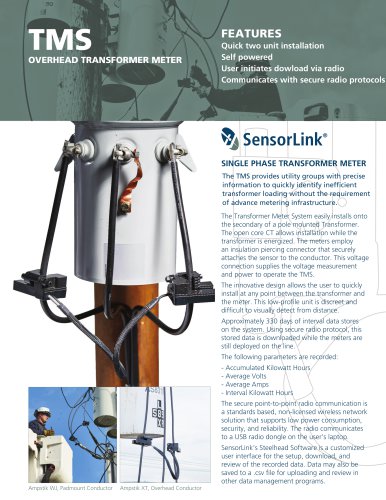 TMS
TMS2 Pages
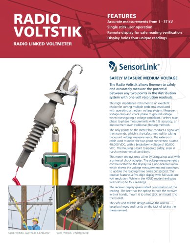 RADIO VOLTSTIK
2 Pages
 Spécification Radio Ampstik
2 Pages
 Spécification Ohmstik Plus
2 Pages
 Spécification Ampstik Plus
2 Pages
 Spécification Ampli Litewire
2 Pages
 Spécification AMCORDER UG
2 Pages
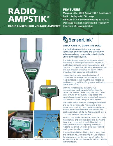
 Ampstik® +
16 Pages
 Amp Litewire
17 Pages
 Recording Ammeter
20 Pages
 Recording Ammeter
20 Pages

- Power supply unit
- DC power supply
- AC/DC power supply
- Measuring device
- Electrical power supply connector
- Tabletop power supply
- Cable connector
- Optical cable
- Coaxial connector
- Power meter
- Single-phase electric energy meter
- Carrying case
- Radio receiver
- Measuring instrument with display
- Adapter power supply
- Compact receiver
- Rugged receiver
- Power supply with USB outlet
- Current measuring module