- Catalogs
- SENSORLINK
- Ampstik® +
Ampstik® +
1 /16Pages

Ampstik® +
1 /16Pages
Catalog excerpts
Operators Manual Slip-on Ammeters
Open the catalog to page 1
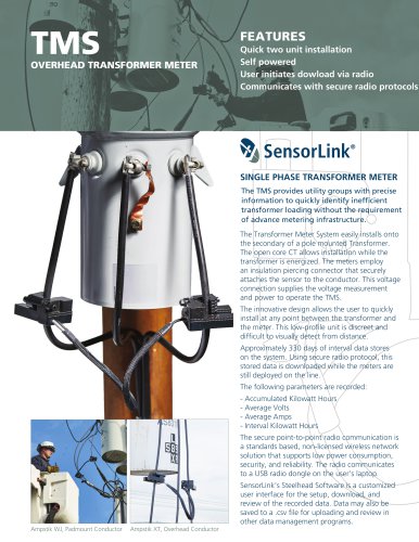
Pad-mounted current measurement Ampstik®+, Model 8-024-PLUS, Wide Jaw Sensor Opening Overhead current measurement ® Ampstik +, Model 8-020-XT PLUS, Standard Sensor Opening
Open the catalog to page 2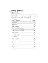
Table of Contents Page Taking a Measurement: RUN Mode 6-7 Taking a Measurement: HOLD Mode 8-9 High Voltage operation 12 Quality Assurance Back Cover
Open the catalog to page 3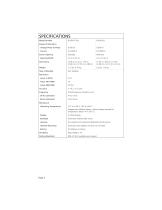
Model Number Range of Operation Voltage Phase to Phase Current Sensor Opening Opening Width Dimensions Type of Reading Resolution Amps .5-99.9A Amps 100-1999A Amps 2000-5000 Accuracy Frequency 50 Hz Calibrated 60 Hz Calibrated Mechanical Operating Temperature Hotstick Mounting Battery Durability Testing Standards Four readings ± 1%, ± 2 Counts Actual frequency marked on unit 47 to 53 Hz 57 to 63 Hz Shipped with Alkaline battery. Lithium battery required for temperatures below -4° F (-20° C) Automatic ambient light sensor Fire resistant and waterproof polycarbonate & silicone Universal chuck adapter....
Open the catalog to page 4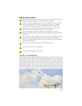
Safety Information Read all safety and instruction statements before using the product. Failing to follow the safety guidelines can cause severe injury or death. Ampstik+ units are designed for use on live, overhead lines with 0 to 500KV. All procedures appropriate for the line voltage are to be taken, including proper work techniques, equipment, and Personal Protection Equipment. The Ampstik+ should be used only by certified personnel who have been trained for live-line, high voltage work by their organization. The hot stick length must be the correct for line voltage per minimum approach distances...
Open the catalog to page 5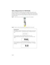
Take a Measurement in RUN Mode When in RUN MODE, the reading continuously changes as the current on the conductor changes. The unit is immediately in the RUN mode after powering on. To place the instrument into the RUN mode from a different mode, press and hold the control switch and scroll to the option RUN, then release the control switch to engage the option. Step 1: Attach the unit to a hot stick with a universal chuck adapter. Step 2: Power on the unit by pressing and releasing the control switch. STARTUP TEST The Ampstik+ conducts a startup test to verify the sensor and circuitry is functioning...
Open the catalog to page 6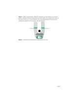
Step 3: Take a measurement. Place the Ampstik+ on the conductor as shown below, with the conductor positioned anywhere below the measurement lines on the arms of the unit. If the conductor cannot be placed below the bump-outs, readings are taken but the accuracy may be lessened. Step 4: Observe the readings being displayed on the unit.
Open the catalog to page 7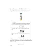
Take a Measurement in HOLD Mode When in HOLD mode, the unit will automatically measure and hold up to four unique current readings Step 1: Attach the unit to a hot stick with a universal chuck adapter. Step 2: Power on the unit by pressing and releasing the control switch. STARTUP TEST The Ampstik+ conducts a startup test to verify the sensor and circuitry is functioning correctly. The following screens will display during the test: --If the test detects a failure, the display will show FAIL and a corresponding code as per below. See page 13 for the failure code chart. 1 If the test determines...
Open the catalog to page 8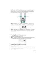
Step 4: Take a measurement. Place the Ampstik+ on the conductor as shown below, with the conductor positioned anywhere below the measurement lines on the arms of the unit. If the conductor cannot be placed below the measurement line, readings are taken but the accuracy may be lessened. Step 5: Hold the unit on the conductor for 2-4 seconds and then remove from the line. The measurement has been taken and the unit is ready to take the next reading. Each reading is numbered and displayed on the top left of the display. 1 Step 6: Repeat steps 4 & 5 to acquire up to three more readings. If the Ampstik+...
Open the catalog to page 9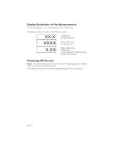
Display Resolution of the Measurements The unit will display to .1A in RUN mode and .3A in HOLD mode. The display resolution changes on the following ranges: 2000 to 5000 Amps 2.00 kAmps 10 Amp resolution (2 decimal places indicates kAmp range) Powering off the unit Step 1: Press and hold the control switch until the OFF option appears and release the switch. The unit is now powered off. The Ampstik+ will power itself off after approximately 20 minutes of inactivity.
Open the catalog to page 10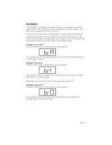
Backlight The Backlight on the Ampstik+ is designed to automatically power on when the ambient light is low. This helps users view the display in low-light situations. The light sensor is located on the front of the unit. The user may see some flicker if the backlight is on when under artificial lighting By default, the Ampstik+ will start in Auto on/off mode on each power on. The modes may be changed manually during use of the unit. The unit will return to the measurement mode the unit was in before the backlight change. Backlight: auto on/off Press the control switch until the following screen...
Open the catalog to page 11
Battery Replacement The Ampstik+ is powered by a single 9V battery. The battery should be replaced when the “LO BAT” indication shows on the display. To change the battery, loosen the screw on the battery cover at the rear of the unit. Pull the battery out of the compartment and install a fresh battery. Secure the cover by closing and tightening the screw on the battery cover. Cleaning The Ampstik+ can be cleaned by wiping with a silicone hot stick wipe to remove sand, salt, and dirt. High Voltage Operation This instrument is designed to operate in high voltage fields. However, difficulty may...
Open the catalog to page 12
Troubleshooting the Ampstik Plus Unit will not power on Verify there is a fresh 9V battery in the unit. Backlight Flicker Due to the refresh rate of the light, some users may see flicker if the backlight is on when under artificial lighting. Fail Codes The unit will not enter into measurement mode if the self-test has any of the below failures. The unit will need to be returned to SensorLink for repair evaluation. FAIL CODE "1": Break to the main current sensor FAIL CODE "2": Break to a current sensor component FAIL CODE "3": Circuit failure FAIL CODE "4": Circuit failure Incorrect readings Verify...
Open the catalog to page 13All SENSORLINK catalogs and technical brochures
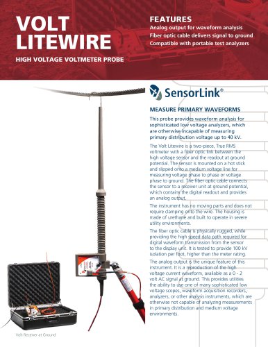 VOLT LITEWIRE
2 Pages
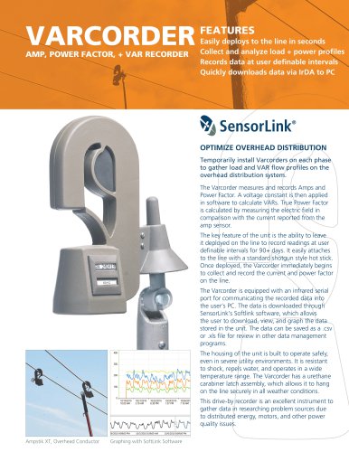 VARCORDER
2 Pages
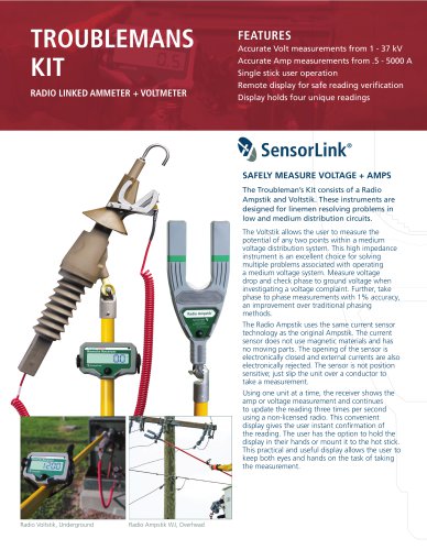 TROUBLEMANS KIT
2 Pages
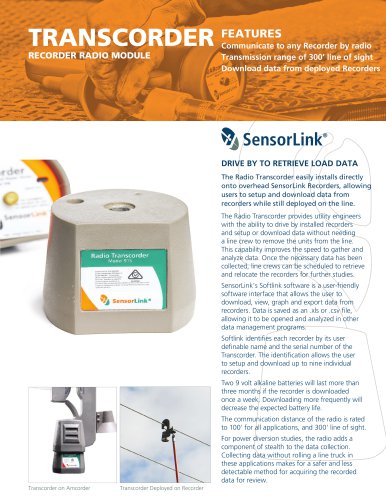 TRANSCORDER
2 Pages
 TMS
TMS2 Pages
 RADIO VOLTSTIK
2 Pages
 Spécification Radio Ampstik
2 Pages
 Spécification Ohmstik Plus
2 Pages
 Spécification Ampstik Plus
2 Pages
 Spécification Ampli Litewire
2 Pages
 Spécification AMCORDER UG
2 Pages
 Ohmstik PLUS
20 Pages
 Amp Litewire
17 Pages
 Recording Ammeter
20 Pages
 Recording Ammeter
20 Pages
- Connector
- Power supply unit
- DC power supply
- AC/DC power supply
- Measuring device
- Electrical power supply connector
- Tabletop power supply
- Cable connector
- Optical cable
- Coaxial connector
- Power meter
- Single-phase electric energy meter
- Carrying case
- Radio receiver
- Measuring instrument with display
- Adapter power supply
- Compact receiver
- Rugged receiver
- Power supply with USB outlet
- Current measuring module