- Catalogs
- SENSORLINK
- Amp Litewire
Amp Litewire
1 /17Pages
Amp Litewire
1 /17Pages
Catalog excerpts
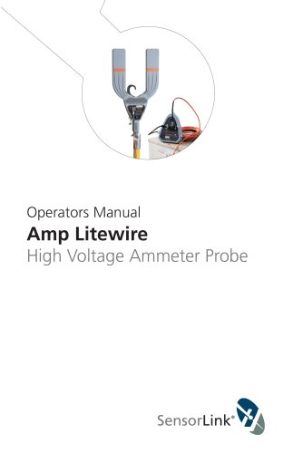
Operators Manual Amp Litewire High Voltage Ammeter Probe
Open the catalog to page 1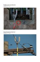
Padmount Conductor Model 8-117XT Overhead Conductor Model 8-117WJ
Open the catalog to page 2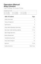
Table of Contents Page Table of Contents Page Amp Litewire Operating Instructions 7-10 Fiber Optic Cable Handling Guidlines 11-12 High Voltage Operation 12 Quality Assurance Back Cover
Open the catalog to page 3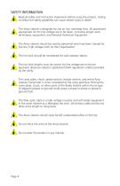
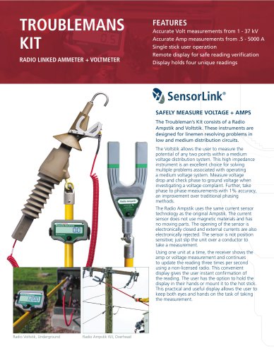
SAFETY INFORMATION Read all safety and instruction statements before using the product. Failing to follow the safety guidelines can cause severe injury or death. The Amp Litewire is designed for use on live, overhead lines. All procedures appropriate for the line voltage are to be taken, including proper work techniques, equipment, and Personal Protection Equipment. The Amp Litewire should be used by personnel who have been trained for live-line, high voltage work by their organization. The hot stick should be considered the sole isolation device. The hot stick lengths must be correct for line...
Open the catalog to page 4
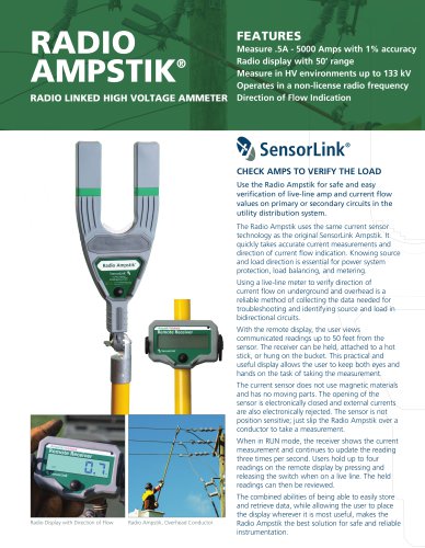
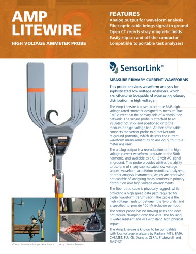
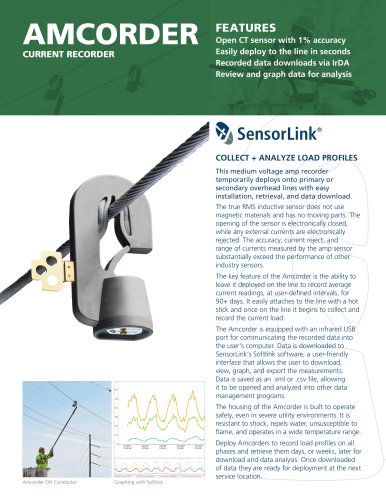
THEORY OF OPERATION The Amp Litewire is a two piece, True RMS Ammeter with a fiber optic link between the high voltage amp sensor transmitter and the analog output at ground potential. The amp sensor transmitter is mounted on a hot stick (insulated pole) and slipped over a low or high voltage line. A fiber optic cable connects the amp sensor transmitter to a receiver unit at ground potential, which provides the analog output. An analog replica of the current waveform is available at the BNC connector. This signal may be read with any instrument that is capable of reading 0-2 volt AC. The unit...
Open the catalog to page 5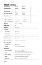
Sensor Opening Standard Wide Jaw Opening Width Transmitter WeightRange of Operation Current Phase to Phase Voltage Phase to Ground Voltage Accuracy Phase Angle Resolution Frequency 50Hz Calibrated 60Hz Calibrated Analog Output Output Connector Output Impedance Frequency Response Fiber Optic Cable Standard Length Isolation Mechanical Ambient Temperature Hotstick Mounting Battery Battery Life 1 millivolt RMS per Amp BNC. No DC offset voltage. Lithium battery required for use below -4°F (-20° C) Fire resistant and waterproof polycarbonate and silicone Universal Chuck Adaptor (hot stick not included)...
Open the catalog to page 6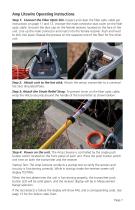
Amp Litewire Operating Instructions Step 1: Connect the Fiber Optic link. Inspect and clean the fiber optic cable per instructions on page 11 and 12. Uncover the male connector dust cover on the fiber optic cable. Uncover the dust cap on the female receiver, located on the face of the unit. Line up the male connector and insert into the female receiver. Push and twist to lock into place. Repeat the process on the opposite end of the fiber for the other unit. Step 2: Attach unit to the hot stick. Attach the sensor transmitter to a universal hot stick (Insulated Pole). Step 3: Attach the Strain...
Open the catalog to page 7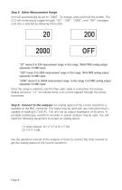
Step 5: Select Measurement Range. Unit will automatically be set to “2000”. To change, press and hold the button. The LCD will continuously toggle through “20”, “200”, “2000”, and “OFF” messages until one is selected by releasing the button. “20” means 0 to 20A measurement range. In this range, 100mV RMS analog output represents 1A RMS input. “200” means 0 to 200A measurement range. In this range, 10mV RMS analog output represents 1A RMS input. “2000” means 0 to 2000A measurement range. In this range, 1mV RMS analog output represents 1A RMS input. Once the range is selected, and the fiber optic...
Open the catalog to page 8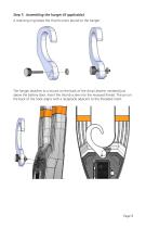
Step 7: Assembling the hanger (if applicable). A retaining ring keeps the thumb screw bound to the hanger. The hanger attaches to a mount on the back of the Amp Litewire, centered just above the battery door. Insert the thumb screw into the recessed thread. The pin on the back of the hook aligns with a receptacle adjacent to the threaded insert.
Open the catalog to page 9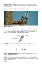
Step 8: Hanging the Transmitter. A detachable hook, ordered separately, is available to allow the amp sensor transmitter and its hot stick to hang temporarily from overhead wires. **The unit should never be left unattended while hanging. **The receiver unit should never be allowed to hang free. Directional Properties The Amp sensor on the Litewire is direction sensitive. In order to ensure proper phase relationship when comparing to a voltage reference, place the Amp Litewire so the face of the instrument is facing the load. The proper phase angle should be 0 to ±90º when measuring the fundamental....
Open the catalog to page 10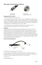
Fiber Optic Cable Handling Guidelines Keeping Ferrites Covered 1. Do not touch the ceramic ferrite end. 2. Cover the fiber optic connector when not in use. Unprotected connector ends are most often damaged by impact, such as hitting the floor. The provided tethered dust cap will protect the connector’s ceramic ferrite end from impact damage that might crack or chip the polished surface. Please contact SensorLink Corporation for a replacement if the provided dust cap is lost or broken. 3. The fiber end face, ceramic ferrite, and dust cap must be clean and it is recommended they be cleaned each...
Open the catalog to page 11
1. Fold the tissue twice so it is four layers thick. 2. Saturate the tissue with alcohol. 3. Clean the sides of the connector ferrule. Place the connector ferrule in the tissue. Apply pressure to the sides of the ferrule. Rotate the ferrule several times to remove all contamination from ferrule sides. 4. Move to a clean, saturated part of the tissue. Put the tissue against the end of the connector ferrule. Put your fingernail against the tissue so that it is directly over the ferrule. 5. (Optional) Use the microscope to verify the quality of the cleaning. If it isn't completely clean, repeat...
Open the catalog to page 12
Troubleshooting Guide Fail Codes The unit will not enter into measurement mode if the self-test has any of the below failures. The unit will need to be returned to SensorLink for repair evaluation. FAIL CODE "1": Break to the main current sensor FAIL CODE "2": Break to a current sensor component FAIL CODE "3": Circuit failure, low gain FAIL CODE "4": Circuit failure, high gain Why does the receiver display show “No Signal”? No data output to the analyzer? This indicates there is not data output to the analyzer. a. Make sure the amp sensor transmitter is powered on. b. Make sure the battery in...
Open the catalog to page 13All SENSORLINK catalogs and technical brochures
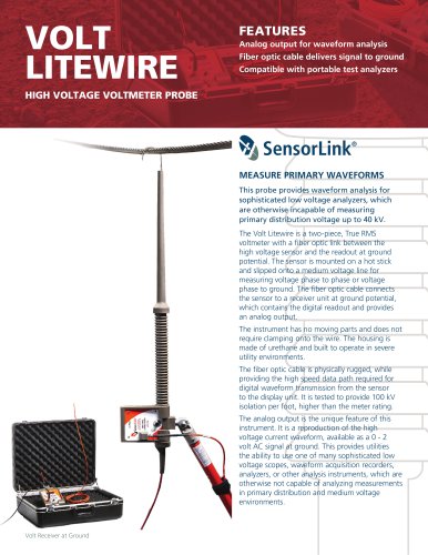 VOLT LITEWIRE
2 Pages
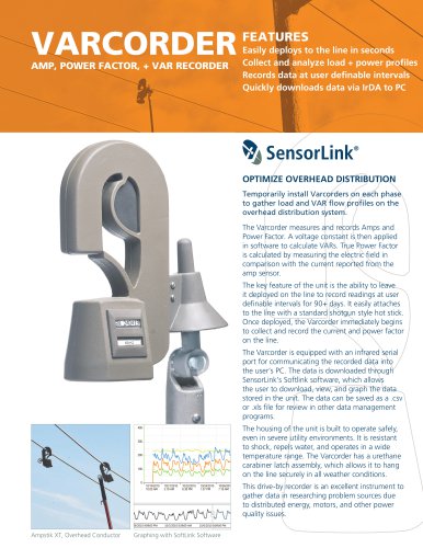 VARCORDER
2 Pages
 TROUBLEMANS KIT
2 Pages
 TRANSCORDER
2 Pages
 TMS
TMS2 Pages
 RADIO VOLTSTIK
2 Pages
 Spécification Radio Ampstik
2 Pages
 Spécification Ohmstik Plus
2 Pages
 Spécification Ampstik Plus
2 Pages
 Spécification Ampli Litewire
2 Pages
 Spécification AMCORDER UG
2 Pages
 Ohmstik PLUS
20 Pages
 Ampstik® +
16 Pages
 Recording Ammeter
20 Pages
 Recording Ammeter
20 Pages

- Power supply unit
- DC power supply
- AC/DC power supply
- Measuring device
- Electrical power supply connector
- Tabletop power supply
- Cable connector
- Optical cable
- Coaxial connector
- Power meter
- Single-phase electric energy meter
- Carrying case
- Radio receiver
- Measuring instrument with display
- Adapter power supply
- Compact receiver
- Rugged receiver
- Power supply with USB outlet
- Current measuring module