- Catalogs
- SensoPart Industriesensorik GmbH
- SensoPart Application guide Best practices for typical application
- Company
- Products
- Catalogs
- News & Trends
- Exhibitions
SensoPart Application guide Best practices for typical application
1 /27Pages

SensoPart Application guide Best practices for typical application
1 /27Pages
Catalog excerpts

SensoPart Application guide Best practices for typical applications Vision sensors Optical sensors Ultrasonic sensors Inductive sensors
Open the catalog to page 1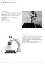
Picking from load carrier Application guide The application. In this application, objects are picked from a load carrier and stacked in a different location. For this purpose, the load carrier is localized in position and rotation. An image of the object is taken above each compartment to obtain the exact coordinates. ▪ Vision sensor: VISOR® V20 Robotic Professional ▪ Lens: Integrated ▪ Focal length: Medium ▪ Field of view: 100 x 120 mm ▪ Working distance: 380 mm ▪ Accuracy: <±0.1 mm (inaccurate gripping and depositing due to vacuum gripper). Calibration. "Hand-Eye (Robotics)" is selected as...
Open the catalog to page 2
Picking from load carrier Application guide VISOR® settings: The following table shows the telegram settings in SensoConfig. To gripping position: Move to gripping position, read robot touchpad and enter in offset dialog to calculate offset. To origin of the robot coordinate system Ethernet TCP/IP Separator Data output Link to example video: https://www.youtube.com/watch?v=tH_dMylblac Note: This document shows an implementation proposal for the described application. This is without guarantee, alternative implementations are possible.
Open the catalog to page 3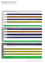
Picking from load carrier Robot programming - Preparation Basic settings of VISOR® and robot: Job "Load_carrier.job" and job "Object.job" must have the same working distance to save cycle time . Therefore it is ߛ necessary to start with the larger field of view. Step 1 Set TCP, weight and center of gravity. Insert load carrier. Teach the image acquisition position with the largest required field of view (load carrier or object). Set up Image acquisition parameters. From now on the working distance must not be adjusted any more. Basic settings VISOR® and robot completed. Perform calibration: Step...
Open the catalog to page 4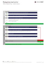
Picking from load carrier Robot programming - Implementation Frame Shift: Step 1 Move to image acquisition position over corner of the load carrier. Capture an image and obtain the position of the charge carrier. Correct the frame by shifting the charge carrier. By using the 3D offset to the frame origin in the job "Load_carrier.job" the VISORȂ directly outputs the new frame position: Frame = VISOR Output. ּ Frame shifting complete. Approach object: Step 1 Move to image acquisition position above load carrier compartment. Capture an image and obtain object position. The image acquisition position...
Open the catalog to page 5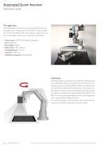
Automated Screw Insertion Application guide The application. In this application, screws are to be inserted with the aid of an automatic screw driving machine. The VISOR® is used to obtain the correct 3D position of the screw hole. An image of any contour on the object is taken and a frame shift is performed. ▪ Vision sensor: VISOR® V20 Robotic Professional ▪ Lens: Integrated ▪ Focal length: Medium ▪ Field of view: 100 x 100 mm ▪ Working distance: 315 mm ▪ Accuracy: <±0.1 mm ▪ Additional component: Polarizing filter Calibration: Hand-Eye (robotics)" was selected as calibration method because...
Open the catalog to page 6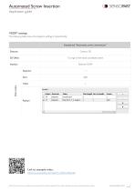
Automated Screw Insertion Application guide VISOR® settings. The following table shows the telegram settings in SensoConfig. Example job "Automated_screw_insertion.job " Detector To origin of the robot coordinate system Ethernet TCP/IP Separator Data output Link to example video: https://www.youtube.com/watch?v=dGWvsNEwTe8 Note: This document shows an implementation proposal for the described application. This is without guarantee, alternative implementations are possible.
Open the catalog to page 7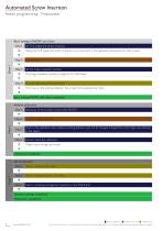
Automated Screw Insertion Robot programming - Preparation Basic settings of VISOR® and robot: Step 1 Set TCP, weight and center of gravity. Setting the TCP, weight and center of gravity is very important in this application, because force mode is used. Insert object. Set the image acquisition position. The image acquisition position is taught in the "shift frame". Set up Image acquisition parameters. From now on the working distance / focus must not be adjusted any more. Basic settings VISOR® and robot completed. Perform calibration: Step 1 Setting up communication (robot with VISOR®). Place...
Open the catalog to page 8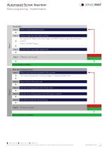
Automated Screw Insertion Robot programming - Implementation Frame Shift: Step 1 Move to image acquisition position. Capture image and retain object position. By using the 3D offset to the frame origin, the VISORȂ directly outputs the new frame position: Frame = VISOR Output. Correct frame using object displacement. Difference small enough? Frame shifting complete. Start the screwing process: Step 1 Move to the screw pick-up position. Pick up screw. The screw pickup position should be taught in a separate (fixed) frame. Move in front of the screw hole. Start the screwing process. Feed in force...
Open the catalog to page 9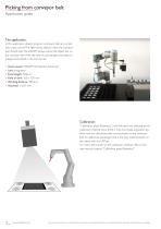
Picking from conveyor belt Application guide The application. In this application, objects lying on a conveyor belt are sorted into a load carrier. The light barrier detects when the conveyor belt should stop. The VISOR® locates where the object lies on the conveyor belt. With the help of a jaw gripper, the object is gripped and placed in the load carrier. ▪ Vision sensor: VISOR® V20 Robotic Advanced ▪ Lens: Integrated ▪ Focal length: Medium ▪ Field of view: 100 x 120 mm ▪ Working distance: 380 mm ▪ Accuracy: <±0.1 mm. Calibration: “Calibration plate (Robotics)" (with fiducials) was selected...
Open the catalog to page 10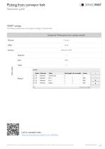
Picking from conveyor belt Application guide VISOR® settings. The following table shows the telegram settings in SensoConfig. Example job "Picking_parts_from_conveyor_belt.job" Detector Ethernet TCP/IP Separator Start Data output Link to example video: https://www.youtube.com/watch?v=UYd_eFOEV6U Note: This document shows an implementation proposal for the described application. This is without guarantee, alternative implementations are possible.
Open the catalog to page 11
Picking from conveyor belt Robot programming - Preparation Basic settings of VISOR® and robot: Step 1 Set TCP, weight and center of gravity. Place object on conveyor belt. Set the image acquisition position. Image acquisition position and calibration position must be the same pose during this calibration. Set up image acquisition parameters. From now on the working distance / focus must not be adjusted any more. Basic settings VISOR® and robot completed. Perform calibration: Set up communication (robot with VISOR®). In the example video the calibration was carried out with the help of the SensoPart...
Open the catalog to page 12All SensoPart Industriesensorik GmbH catalogs and technical brochures
 BlueLight - The NEW standard
12 Pages


- Visible imager
- Industrial camera module
- Monitoring camera system
- Full-color camera system
- Proximity switch
- Detection camera system
- Image processing camera module
- Monochrome camera module
- Cylindrical proximity sensor
- Inductive proximity sensor
- Inspection imager
- Photoelectric sensor
- High-speed camera module
- Rectangular photoelectric sensor
- Distance sensor
- Machine vision video camera
- Medical video camera
- Threaded proximity sensor
- Camera for the automotive industry
- Rectangular proximity sensor