Catalog excerpts

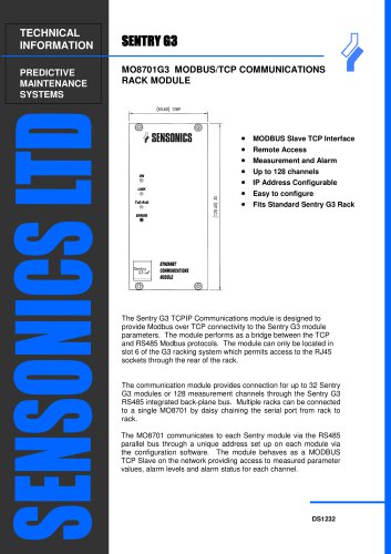
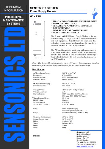
TECHNICAL INFORMATION CONDITION MONITORING SOLUTIONS Sentry G3 Machinery Protection Monitor The Sentry G3 Machinery Protection Monitor is a high performance signal conditioning unit; providing a universal platform for the interfacing of various sensor types in compliance with the API 670 standard. Each of the four channels can be independently programmed to provide continuous monitoring and protection facilities across a broad spectrum of measurement regimes (including vibration, expansion, temperature, speed, etc). Utilising the latest DSP technology, once a channel is set up and running, the resulting alarm relay and analogue output facilities are independent from the remaining module functionality, resulting in a scalable high integrity configuration. The module is provided with an intuitive colour LCD display and drive facility to provide immediate viewing and access to the machine parameters. Several modes of display are available including bar graph, FFT and an alarm historian. The module provides the necessary power source for the selected transducer, providing for 2 (ICP type) or 3 – wire accelerometer variants, ± 24V proximity probe systems, LVDTs and a range of speed & temperature sensors. Each transducer signal is buffered and available via the front panel analogue connection arrangement and a USB interface is provided for programming of the unit and storage of channel history and settings. The unit is designed for mounting in a custom 19 inch rack assembly which also contains a dual redundant power supply option. The G3 system offers excellent channel density with up to 24 measurement channels in a 3U format. Each channel can provide independent analogue outputs of current and voltage for DCS connection in addition to an alarm relay. Further alarm relay expansion is possible through connection to digital outputs at the rear of the module. Machine Measurement Modes Absolute and Relative Vibration Displacement and Thrust Position Speed, Phase and Reverse Rotation Differential and Casing Expansion Rod Drop Temperature Turbine Specialist Measurement Modes Shaft Eccentricity Differential Ramp Expansion Rotor / Stator Air Gap Overspeed LPF, HPF, Tracking and Notch Filters Programmable Warning and Danger Alarms with Relay Logic Cross-Channel Voting Harmonic and Phase Analysis Programmable Transducer Supply Scaleable Module Hardware with plug in DSP card, up to four channels Dual Redundant Power Supply USB Programmable Dual Redundant Modbus RS48
Open the catalog to page 1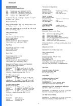
Transducer Configurations Absolute Vibration Selectable Measurement Modes AM1 AM2 AM3 AM4 Accelerometer Sensitivity Range Standard ICP option 3/4 – wire option Select from Acceleration (m/s or g), Velocity (mm/s or ips) and Displacement (um or mil). Select from average, rms, pk, pk to pk, pk / rms or dB referenced to 20Log10(1.0V). Relative Vibration Selectable Measurement Modes Filter Characteristics Low Pass Programmable 3dB, 100Hz to 10kHz Roll off >24dB / Octave Setting resolution 1% Tracking ratio of 0.1 to 10 of incoming Tacho Tacho division (multi tooth wheel) 1 to 60 Overall Level,...
Open the catalog to page 2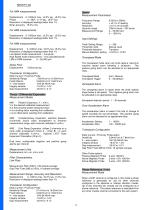
Speed Measurement Parameters Displacement 0–1000um max, ±2.0% typ, ±5.0% max Phase 0 - 360º, ±1.0º typ, ±5.0º max Resolution of displayed readings better than 1% Smax accuracy ±5.0% max Frequency Range Accuracy Resolution Dynamic range Measurement Range Displacement 0–1000um max, ±2.0% typ, ±5.0% max Resolution of displayed readings better than 1% Input Settings Teeth Setting Range Threshold mode Threshold detection Manual detection setting Displacement 0–1000um max, ±2.0% typ, ±5.0% max Resolution of displayed readings better than 1% Low Speed mode measurement – true pk-pk High Speed mode...
Open the catalog to page 3
Measurement Parameters Temperature Measurement Mode Frequency Range Accuracy Resolution Dynamic range Measurement Range Two channels of temperature measurement are available for each DSP channel. The DSP channel is fixed to a particular sensor type. Buffered Output 0.02Hz to 20kHz < ±0.1% of reading <±0.1% of full scale 100mV pk-pk – 20V pk-pk 0 – 50,000 rpm 0 – 1000 Hz TTL Measurement Units Temperature ºC or ºF Input Settings Measurement Range, Accuracy and Resolution Threshold mode Threshold detection Manual detection setting Manual Positive Edge +19.0V to -19.0V Transducer Configuration...
Open the catalog to page 4
Measurement Range, Accuracy and Resolution Forward and Reverse Alarm Gap 2–32mm, ±1.0% typ, ±2.0% max Resolution of displayed readings shall be < 1% Two alarms are available to provide the status of the rotating shaft. Each alarm can be allocated to an appropriate relay. Gap measurement provided for average, maximum and minimum with pole number for max and min. Zerospeed Alarm No. of Poles or samples per revolution, 2 to 128. The zerospeed alarm is raised when the shaft rotation drops below a set speed. This negative going alarm can be allocated to an appropriate relay. Transducer...
Open the catalog to page 5
Front Panel Facilities Channel Defeat Colour LCD display Size 43mm x 57mm Resolution 240 x 320 pixels Backlight Timeout Function Display Modes 4 Channel Bargraph 4 Channel Traffic Light Measurement + Gap Alarm Matrix Single Channel Trend 500,000 points per channel Downloadable to .csv format Alarm Log 500 entries USB Type B Interface Windows XP compatible Menu Button Drive Button Buffered Outputs Individual channels can be configured to defeat parameter alarms in the event of an integrity alarm. During defeat all other channel interfaces operate as normal. Alarm Historian All alarm events...
Open the catalog to page 6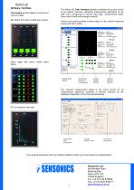
' Sentry G3 Offline Mode ftte Med* Catfuyji&xft Lceree System vnw Hob Module Status Alarm Relay Module Channel Window Status and Display Summary Configuration Facility Windows Chamel Name Latchng hjitte>esis Delay Outputs Control Alarm Panel
Open the catalog to page 7All SENSONICS LTD catalogs and technical brochures
-
Aegis
3 Pages


