
- Catalogs
- SENSONICS LTD
- Turbine Supervisory Guide VMS TSI Overspeed

Turbine Supervisory Guide VMS TSI Overspeed

Turbine Supervisory Guide VMS TSI Overspeed
Sensonics specializes in turbine condition monitoring, focusing on vibration and expansion measurement for turbine and auxiliary plant equipment. This guide details their expertise in transducers, measurement techniques, and protection configurations for safe plant shutdowns.
Turbine supervision is essential for power plant operations to detect faults early, enabling predictive maintenance. Sensonics provides sensors and systems for the power generation industry, including techniques like absolute vibration, shaft vibration, eccentricity, differential expansion, valve position, casing expansion, speed, and temperature monitoring.
Accelerometer: Uses piezoelectric crystals for acceleration measurement, with shear mode devices offering low-frequency performance. Velocity Transducer: Provides velocity output without external power, suitable for frequencies between 10 and 1500 Hz. Eddy Current Proximity Probe: Measures shaft/bearing distance variations, available in various types with ranges up to 8mm.
Techniques include absolute vibration, shaft vibration, eccentricity, differential expansion, valve position, casing expansion, speed monitoring, and temperature, aiding in turbine operation monitoring and providing alarms or automated shutdowns.
API Standard 670 outlines protection configurations for safe plant operations, emphasizing robust monitoring systems.
Advanced monitoring includes rod drop, rundown monitoring, and orbit analysis for enhanced protection.
Details on bracketry, cubicle panels, seismic monitoring, and protection equipment are provided.
Offers a guide for product selection and site-specific application references.
The Linear Variable Differential Transformer (LVDT) generates an electrical signal proportional to core displacement, suitable for applications requiring frictionless movement.
LVDT operates on mutual inductance, with core movement generating a differential voltage linearly related to position.
LVDT offers infinite resolution, robustness, and high temperature tolerance, ideal for various measurement applications.
Transducers are selected based on frequency range requirements, with eddy probes for low frequencies, velocity pick-ups for mid-range, and accelerometers for wide frequency ranges.
Vibration is monitored in terms of velocity or displacement, with accelerometers and velocity transducers commonly used.
Monitoring is crucial at low speeds, with techniques like peak hold functions and dual path modules to eliminate errors.
Eddy current probes measure rotor to casing differential expansion, with techniques to extend measurement range.
The document provides a comprehensive overview of LVDT and other transducers, highlighting applications, advantages, and limitations.
API Standard 670 is crucial for monitoring rotating equipment, specifying properties for accelerometers and eddy current probes, emphasizing protection and system integrity.
Protection systems may require adherence to IEC 61508 for SIL, enhancing reliability and failure detection.
Uses advanced eddy current probes for accurate rod position measurement, reliable and economical for retrofitting.
Detects shaft cracks early by monitoring stiffness and deflection changes, preventing costly replacements.
Analyzes orbit shape to detect machine conditions, requiring proper phase marker alignment.
Discusses shaft behavior observed through eddy probes, with oil whirl described as a counter-rotating orbit condition.
Proper mounting is crucial to avoid resonance and false readings, with emphasis on rigid brackets and appropriate probe gapping.
Factors include mounting type, dimensions, cable entry, earthing, and environmental protection, with detailed specifications provided.
Sensonics provides seismic monitoring systems for safety, with components designed for robustness and reliability.
Sensonics offers a wide range of products and services, including customized design, implementation, and maintenance.
For further information or orders, Sensonics can be contacted via phone, fax, or email, with a commitment to constant improvement.
Catalog excerpts

POWER PLANT EQUIPMENT
Open the catalog to page 1
Velocity Transducer Eddy Current Proximity Probe Choosing the right transducer Measurement Techniques Absolute Vibration Eccentricity & Shaft Vibration Rotor Differential Expansion Shaft Position Speed Monitoring Casing & Cylinder Expansion Valve Position Monitoring ] g Auxiliary Plant Monitoring Rundown Monitoring Orbit Analysis Cubicle Panels Protection Equipment Site References 2/ Quick Product Selection Guide
Open the catalog to page 2
SENSONICS PRODUCTS & COMPETENCES Turbine Supervisory Systems For nearly 30 years Sensonics has been supplying Turbine Condition Monitoring solutions to the power generation industry worldwide. Involved in measurement definition through to supply and final system commissioning, our experience within the power sector is second to none. Standalone Monitoring Solutions Accelerometer, Displacement & Seismic Transducers Nuclear Infrastructure Protection We have produced this guide to capture the essence of that experience and to explain the basics of vibration and expansion measurement techniques relating...
Open the catalog to page 3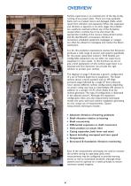
OVERVIEW Turbine supervision is an essential part of the day-to-day running of any power plant. There are many potential faults such as cracked rotors and damaged shafts, which result from vibration and expansion.When this expansion and vibration is apparent in its early stages the problem can usually be resolved without any of the disruption caused when a turbine has to be shut down. By appropriate trending of the various measurement points and the identification of excessive vibration or movement, scheduled equipment stoppages or outages can often be utilised to investigate and resolve the...
Open the catalog to page 4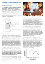
TRANSDUCERS & SENSORS The Accelerometer The accelerometer is based on the electrical properties of piezoelectric crystal. In operation, the crystal is stressed by the inertia of a mass. The variable force exerted by the mass on the crystal produces an electrical output proportional to acceleration. Two common methods of constructing the device to generate a residual force are compression mode and shear mode respectively. A residual force is of course required to enable the crystal to generate the appropriate response, moving in either direction on a single axis. A shear mode construction is illustrated...
Open the catalog to page 6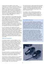
For practical purposes, a typical velocity pick-up is limited to frequencies between approximately 10 and 1500 Hz. This has an advantage in certain applications where high frequency vibration (generated from steam noise for example) can saturate standard accelerometers with a built-in integration function. Accelerometers are available in various output configurations. The industry standard drive utilises a 2wire current source interface operating at a nominal bias voltage of +12Vdc typ., with an output sensitivity of 100mV/g. This configuration limits the dynamic range to around ± 70g, which...
Open the catalog to page 7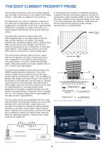
THE EDDY CURRENT PROXIMITY PROBE The principle of operation, as the name implies, depends upon the eddy currents set up in the surface of the target material - shaft, collar, etc. adjacent to the probe tip. The Eddy probe tip is made of a dielectric material and the probe coil is encapsulated within the tip. The coil is supplied with a constant RF current from a separate Eddy Probe Driver connected via a cable, which sets up an electromagnetic field between the tip and the observed Any electrically conductive material within this electromagnetic field, i.e. the target material, will have eddy...
Open the catalog to page 8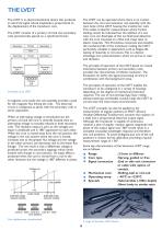
THE L VDT The LVDT is an electromechanical device that produces an electrical signal whose amplitude is proportional to the displacement of the transducer core. The LVDT can be operated where there is no contact between the core and extension rod assembly with the main body of the LVDT housing the transformer coils. This makes it ideal for measurements where friction loading cannot be tolerated but the addition of a low mass core can. Examples of this are fluid level detection with the core mounted on a float and creep tests on elastic materials. This frictionless movement also benefits the mechanical...
Open the catalog to page 9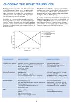
CHOOSING THE RIGHT TRANSDUCER Each type of transducer has an area of measurement in which it is particularly useful. In the figure below, the relationship is clearly shown. Note that the velocity curve is constant. Acceleration (the first derivative of velocity) increases with frequency, while displacement (the first integral of velocity) decreases. Eddy Probe are used for low frequency measurements (typically dc to 1kHz), and the velocity pick-ups cover the mid-frequency band (10Hz to 2kHz). Accelerometers generally have the widest frequency range and certainly the highest (1Hz to 10kHz typically)....
Open the catalog to page 10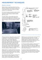
MEASUREMENT TECHNIQUES Absolute vibration Absolute vibration monitoring is perhaps the primary method of machine health monitoring on steam turbines. The type of transducer used is seismic (ie vibration of turbine relative to earth) and can either be a velocity The choice of transducer has been the subject of debate for many years and often the final decision is purely subjective. A number of factors however should be taken into account. The steam turbine is a fairly simple machine when considering vibration signatures.The frequencies of interest are normally from one-half to five times running...
Open the catalog to page 11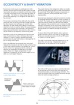
ECCENTRICITY & SHAFT VIBRATION Eccentricity monitoring can be subdivided into shaft vibration and bent shaft monitoring. Bent shafts normally result when the turbine is stationary and thermal arching or bowing of the shaft occurs or the shaft sags under its own weight. The Turbine is rotated slowly (barring) to prevent this happening or to straighten the shaft after it has occurred. The graphs illustrate that misalignment effects are readily ignored through utilising the peak to peak measurements of eccentricity. When higher frequency components are present (e.g hammer marks) the RMS value is...
Open the catalog to page 12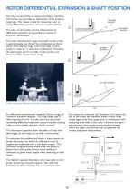
ROTOR DIFFERENTIAL EXPANSION & SHAFT POSITION The eddy current probe, as well as providing ac vibratory information, also provides dc information of the probe to target gap. This makes it ideal for measuring rotor to casing differential expansion via a non-contact method. The eddy current probe and the measurement of differential expansion are governed by a series of empirical relationships. The linear measurement range of an eddy current probe is approximately one third of its coil diameter as shown earlier. The ideal flat target area for an eddy current probe to “observe” is twice the coil...
Open the catalog to page 13All SENSONICS LTD catalogs and technical brochures
 Aegis
Aegis3 Pages



- Proximity switch
- Cylindrical proximity sensor
- Position transducer
- Piezoelectric accelerometer
- Linear position transmitter
- Displacement transducer
- DC proximity sensor
- Single-axis accelerometer
- IEPE accelerometer
- Linear displacement sensor
- Analog position transducer
- Triaxial acceleration sensor
- Real-time monitoring module
- No-contact position sensor
- Measurement monitoring module
- Data acquisition unit
- Signal conditioner
- Temperature monitoring module
- Continuous monitoring module