- Company
- Products
- Catalogs
- News & Trends
- Exhibitions
Temperature Sensor IC STS21
1 /12Pages

Temperature Sensor IC STS21
1 /12Pages
Catalog excerpts
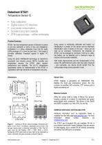
Datasheet STS21 Temperature Sensor IC ■ Fully calibrated ■ Digital output, I2C interface ■ Low power consumption ■ Excellent long term stability ■ DFN type package - reflow solderable Product Summary STS21, the new temperature sensor of Sensirion is about to set new standards in terms of size and intelligence: Embedded in a reflow solderable Dual Flat No leads (DFN) package of 3 x 3mm foot print and 1.1mm height it provides calibrated, linearized signals in digital, I2C format. Using the same CMOSens® technology as Sensirion’s successful and industry proven SHT2x humidity and temperature sensors, the STS21 offers superior performance and reliability. The ±0.2°C temperature specification allows for implementation of the STS21 in applications with high demands on temperature accuracy. Every sensor is individually calibrated and tested. Lot identification is printed on the sensor and an electronic identification code is stored on the chip - which can be read out by command. Furthermore, the resolution of STS21 can be changed by command (11bit up to 14bit), low battery can be detected and a checksum helps to improve communication reliability. With made improvements and the miniaturization of the sensor the performance-to-price ratio has been improved - and eventually, any device should benefit from the cutting edge energy saving operation mode. Bottom View Sensor Chip STS21 features a generation 4C CMOSens® chip. Besides the band gap temperature sensor, the chip contains an amplifier, A/D converter, OTP memory and a digital processing unit. Material Contents While the sensor itself is made of Silicon the sensors’ housing consists of a plated Cu lead-frame and green epoxy-based mold compound. The device is fully RoHS and WEEE compliant, e.g. free of Pb, Cd and Hg. Additional Information and Evaluation Kits Additional information such as Application Notes is available from the web page www.sensirion.com. For more information please contact Sensirion via [email protected]. For STS21 two Evaluation Kits are available: EK-H4, a four-channel device with Viewer Software, that also serves for data-logging, and a simple EK-H5 directly connecting one sensor via USB port to a computer.
Open the catalog to page 1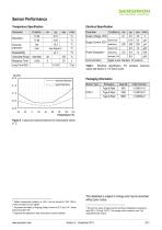
Sensor Performance Temperature Specification This datasheet is subject to change and may be amended without prior notice. 4 Min and max values of Supply Current and Power Dissipation are based on fixed VDD = 3.0V and T<60°C. The average value is based on one 11bit measurement per second.
Open the catalog to page 2
Users Guide STS21 1 Extended Specification On the PCB the I/O lands5 should be 0.2mm longer than the package I/O pads. Inward corners may be rounded to match the I/O pad shape. The I/O land width should match the DFN-package I/O-pads width 1:1 and the land for the die pad should match 1:1 with the DFN package – see Figure 5. Figure 3 Typical dependency of supply current (sleep mode) versus temperature at VDD = 3.0V. Please note that the variance of these data can be above ±25% of displayed value. 20 18 16 The solder mask6 design for the land pattern preferably is of type Non-Solder Mask Defined...
Open the catalog to page 3
the package. The die pad aperture should cover about 70 – 90% of the pad area – say up to 1.4mm x 2.3mm centered on the thermal land area. It can also be split in two openings. Due to the low mounted height of the DFN, “no clean” type 3 solder paste7 is recommended as well as Nitrogen purge during reflow. Furthermore, there are self-heating effects in case the measurement frequency is too high. To keep self heating below 0.1°C, STS21 should not be active for more than 10% of the time – e.g. maximum two measurements per second at 14bit accuracy shall be made. critical zone Figure 7 Top view of...
Open the catalog to page 4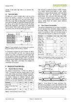
SGNSIRION THE SENSOR COMPANY Table 3 Electrical absolute maximum ratings
Open the catalog to page 5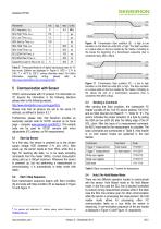
SGNSIRION THE SENSOR COMPANY Table 5 Timing specifications of digital input/output pads for I2C fast mode. Entities are displayed in Figure 9. VDD = 2.1V to 3.6V, T = -40°C to 125°C, unless otherwise noted. For further information regarding timing, please refer to http://www.standardics.nxp.com/support/i2c/. Figure 10 Transmission Start condition (S) - a high to low transition on the SDA line while SCL is high. The Start condition is a unique state on the bus created by the master, indicating to the slaves the beginning of a transmission sequence (bus is considered busy after a Start). Table...
Open the catalog to page 6
SGNSIRION THE SENSOR COMPANY Table 7 Measurement times for T measurements at different resolutions. Typical values are recommended for calculating energy consumption while maximum values shall be applied for calculating waiting times in communication. In the hold master mode, the STS21 pulls down the SCL line while measuring to force the master into a wait state. By releasing the SCL line the sensor indicates that internal processing is terminated and that transmission may be continued. Figure 14 Soft Reset - grey blocks are controlled by STS21.
Open the catalog to page 7
SGNSIRION THE SENSOR COMPANY 5.6 User Register The content of User Register is described in Table 8. Please note that reserved bits must not be changed and default values of respective reserved bits may change over time without prior notice. Therefore, for any writing to the User Register, default values of reserved bits must be read first. Thereafter, the full User Register string is composed of respective default values of reserved bits and the remainder of accessible bits optionally with default or non-default values. Figure 15 Read and write register sequence - grey blocks are controlled...
Open the catalog to page 8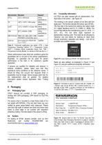
Table 9 Performed qualification test series. HTOL = High Temperature Operating Lifetime, TC = Temperature Cycles, UHST = Unbiased Highly accelerated Stress Test, THB = Temperature Humidity Biased. For details on ESD see Sect. 4.1. Sensor performance under other test conditions cannot be guaranteed and is not part of the sensor specifications. Especially, no guarantee can be given for sensor performance in the field or for customer's specific application. If sensors are qualified for reliability and behavior in extreme conditions, please make sure that they experience same conditions as the reference...
Open the catalog to page 9All Sensirion catalogs and technical brochures
 Antifogging Humidity Sensors
2 Pages
 SDP800/810 Digital
14 Pages
 800/810 Analog
8 Pages
 Liquid Flow Meter LG16
8 Pages
 Liquid Flow Meter LG01
4 Pages
 Liquid Flow Meter LS32-1500
4 Pages
 Liquid Flow Meter SLI
8 Pages
 Liquid Flow Meter SLG
7 Pages
 Liquid Flow Meter SLQ-QT105
6 Pages
 Liquid Flow Meter SLQ-QT500
7 Pages
 Liquid Flow Meter SLS-1500
5 Pages
 Liquid Flow Sensor LPG10
5 Pages
 Liquid Flow Sensor LD20
18 Pages
 STS3x-DIS
18 Pages
 Liquid Flow
5 Pages
 Temperature Sensors
4 Pages
 Humidity Sensors
8 Pages
 Antifogging
2 Pages
 Smart Thermostats
2 Pages
 SHTW2
SHTW214 Pages
 Environmental Sensing
6 Pages
 Datasheet SHTC1
14 Pages
 Datasheet SHT3x digital
21 Pages
 Datasheet SHT3x analog
13 Pages
 LS32-1500
4 Pages
 SHT20
SHT2014 Pages
 Liquid Flow Sensor LG16
5 Pages
 Liquid Flow Sensor LG216
6 Pages


- Flowmeter
- Liquid flow monitor
- Resistance temperature sensor
- Waterproof flow meter
- Gas flow monitor
- Industrial flow monitor
- Pressure probe
- Precision flow meter
- In-line flow meter
- Water flow monitor
- Compact flow monitor
- Gas sensor
- DC flow monitor
- RS485 flow monitor
- Mass flow monitor
- Digital flow monitor
- IP65 flow monitor
- Relative humidity and temperature sensor