Catalog excerpts
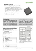
High-Accuracy Digital Temperature Sensor IC ■ Fully calibrated and linearized digital output ■ Wide supply voltage range, from 2.4 V to 5.5 V ■ I2C Interface with communication speeds up to 1 MHz and two user selectable addresses ■ Typical accuracy of up to ± 0.1 °C ■ Very fast start-up and measurement time ■ Tiny 8-Pin DFN package Product Summary The STS3x-DIS is Sensirion's new high accuracy digital temperature sensor. It relies on the industry proven CMOSens® technology, providing for increased intelligence, reliability and improved accuracy specifications compared to its predecessors. Its functionality includes enhanced signal processing, two distinctive and user selectable I2C addresses and communication speeds of up to 1 MHz. The DFN package has a footprint of 2.5 x 2.5 mm2 while keeping a height of 0.9 mm. This allows for integration of the STS3x-DIS into a great variety of applications. Additionally, the wide supply voltage range of 2.4 V to 5.5 V guarantees compatibility with a wide range of applications. All in all, the STS3x-DIS incorporates more than 15 years of Sensirion's digital sensor know-how. Benefits of Sensirion’s CMOSens® Technology ■ High reliability and long-term stability ■ Industry-proven technology with a track record of more than 15 years ■ Designed for mass production ■ High process capability www.sensirion.com November 2017 - Version 2 1/1
Open the catalog to page 1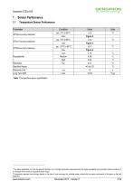
SeNSIRION 1 Sensor Performance1.1 Temperature Sensor Performance Parameter Table 1 Temperature sensor specification. www.sensirion.com November 2017 - Version 2 2/18 The stated repeatability is 3 times the standard deviation (3a) of multiple consecutive measurements at the stated repeatability and at constant ambient conditions. It is a measure for the noise on the physical sensor output. Temperature response times strongly depend on the type of heat exchange, the available sensor surface and the design environment of the sensor in the final application.
Open the catalog to page 2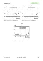
maximal tolerance typical tolerance typical tolerance Figure 2 Temperature accuracy of the STS30 sensor. Figure 3 Temperature accuracy of the STS31 sensor. STS35 DT (°C) ±1.5 maximal tolerance typical tolerance ±1.0 Figure 4 Temperature accuracy of the STS35 sensor.
Open the catalog to page 3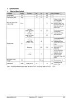
Table 2 Electrical specifications, typical values are valid for T=25°C, min. & max. values for T=-40°C ... 125°C. www.sensirion.com November 2017 - Version 2 4/18
Open the catalog to page 4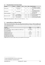
Table 4 Minimum and maximum ratings; values may only be applied for short time periods. 3 According to ANSI/ESDA/JEDEC JS-001-2014; AEC-Q100-002. 4 According to ANSI/ESD S5.3.1-2009; AEC-Q100-011. www.sensirion.com November 2017 - Version 2 5/18
Open the catalog to page 5
3 Pin Assignment The STS3x-DIS comes in a tiny 8-pin DFN package -see Table 5. Table 5 STS3x-DIS pin assignment (transparent top view). Dashed lines are only visible if viewed from below. The die pad is internally connected to ground. 3.1 Power Pins (VDD, VSS) The electrical specifications of the STS3x-DIS are shown in Table 2. The power supply pins must be decoupled with a 100 nF capacitor that shall be placed as close to the sensor as possible - see Figure 5 for a typical application circuit. 3.2 Serial Clock and Serial Data (SCL, SDA) SCL is used to synchronize the communication...
Open the catalog to page 6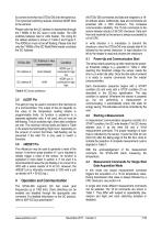
Table 6 I2C device addresses to connect more than two STS3x-DIS onto the same bus. The dynamical switching requires individual ADDR lines to the sensors. Please note that the I2C address is represented through the 7 MSBs of the I2C read or write header. The LSB switches between read or write header. The wiring for the default address is shown in Table 6 and Figure 5. The ADDR pin must not be left floating. Please note that only the 7 MSBs of the I2C Read/Write header constitute the I2C Address. 3.5 ALERT Pin The alert pin may be used to connect to the interrupt pin of a microcontroller. The...
Open the catalog to page 7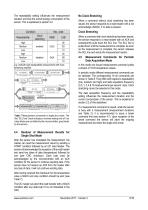
The repeatability setting influences the measurement duration and thus the overall energy consumption of the sensor. This is explained in section 2.2. Condition When a command with clock stretching has been issued, the sensor responds to a read header with an ACK and subsequently pulls down the SCL line. The SCL line is pulled down until the measurement is complete. As soon as the measurement is complete, the sensor releases the SCL line and sends the measurement results. High 06 Medium enabled 0x2C 0D Low 10 High 00 Medium disabled 0x24 0B Low 16 e.g. 0x2C06: high repeatability measurement...
Open the catalog to page 8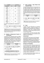
Table 9 Fetch Data command (clear blocks are controlled by the microcontroller, grey blocks by the sensor) Table 10 Break command (clear blocks are controlled by the microcontroller, grey blocks by the sensor). 4.6 Readout of Measurement Results for Periodic Mode Transmission of the measurement data can be initiated through the fetch data command shown in Table 9. If no measurement data is present the I2C read header is responded with a NACK (Bit 9 in Table 9) and the communication stops. After the read out command fetch data has been issued, the data memory is cleared, i.e. no measurement...
Open the catalog to page 9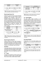
CommandHex Code Soft Reset 0x30A2 Table 15 Command to clear the status register (clear blocks are controlled by the microcontroller, grey blocks by the sensor) www.sensirion.com November 2017 - Version 2 10/18
Open the catalog to page 10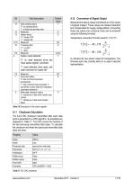
Table 16 Description of the status register. 4.12 Conversion of Signal Output Measurement data is always transferred as 16-bit values (unsigned integer). These values are already linearized and compensated for supply voltage effects. Converting those raw values into a physical scale can be achieved using the following formulas. Temperature conversion formula (result in °C & °F): o T [°C ] = - 45 +175 T [°F] = - 49 + 315 ST denotes the raw sensor output for temperature. The formulas work only correctly when ST is used in decimal representation. 4.11 Checksum Calculation The 8-bit CRC...
Open the catalog to page 11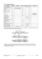
Table 18 Timing specifications for I2C communication, valid for T=-40°C ... 125°C and Vdd.i™ ... Vdd, max. The nomenclature above is according to the I2C specification (UM10204, Rev. 6, April 4, 2014). thHIGH tl_OW spaggfc Figure 6 Timing diagram for digital input/output pads. SDA directions are seen from the sensor. Bold SDA lines are controlled by the sensor, plain sDA lines are controlled by the micro-controller. Note that SDA valid read time is triggered by falling edge of preceding toggle. www.sensirion.com November 2017 - Version 2 12/18
Open the catalog to page 12All Sensirion catalogs and technical brochures
-
Antifogging Humidity Sensors
2 Pages
-
SDP800/810 Digital
14 Pages
-
800/810 Analog
8 Pages
-
Liquid Flow Meter LG16
8 Pages
-
Liquid Flow Meter LG01
4 Pages
-
Liquid Flow Meter LS32-1500
4 Pages
-
Liquid Flow Meter SLI
8 Pages
-
Liquid Flow Meter SLG
7 Pages
-
Liquid Flow Meter SLQ-QT105
6 Pages
-
Liquid Flow Meter SLQ-QT500
7 Pages
-
Liquid Flow Meter SLS-1500
5 Pages
-
Liquid Flow Sensor LPG10
5 Pages
-
Liquid Flow Sensor LD20
18 Pages
-
Temperature Sensor IC STS21
12 Pages
-
Liquid Flow
5 Pages
-
Temperature Sensors
4 Pages
-
Humidity Sensors
8 Pages
-
Antifogging
2 Pages
-
Smart Thermostats
2 Pages
-
SHTW2
14 Pages
-
Environmental Sensing
6 Pages
-
Datasheet SHTC1
14 Pages
-
Datasheet SHT3x digital
21 Pages
-
Datasheet SHT3x analog
13 Pages
-
LS32-1500
4 Pages
-
SHT20
14 Pages
-
Liquid Flow Sensor LG16
5 Pages
-
Liquid Flow Sensor LG216
6 Pages


