- Company
- Products
- Catalogs
- News & Trends
- Exhibitions
SHT20
1 /14Pages

SHT20
1 /14Pages
Catalog excerpts

Datasheet SHT20 Humidity and Temperature Sensor IC Fully calibrated Digital output, I2C interface Low power consumption Excellent long term stability DFN type package – reflow solderable Product Summary SHT20, the new humidity and temperature sensor of Sensirion is about to set new standards in terms of size and intelligence: Embedded in a reflow solderable Dual Flat No leads (DFN) package of 3 x 3mm foot print and 1.1mm height it provides calibrated, linearized signals in digital, I2C format. With a completely new designed CMOSens® chip, a reworked capacitive type humidity sensor and an improved band gap temperature sensor the performance has been lifted even beyond the outstanding level of the previous sensor generation (SHT1x and SHT7x). For example, measures have been taken to stabilize the behavior at high humidity levels. Dimensions Every sensor is individually calibrated and tested. Lot identification is printed on the sensor and an electronic identification code is stored on the chip – which can be read out by command. Furthermore, the resolution of SHT20 can be changed by command (8/12bit up to 12/14bit for RH/T), low battery can be detected and a checksum helps to improve communication reliability. With made improvements and the miniaturization of the sensor the performance-to-price ratio has been improved – and eventually, any device should benefit from the cutting edge energy saving operation mode. For testing SHT20 a new evaluation Kit EK-H4 is available. SHT20 features a generation 4C CMOSens® chip. Besides the capacitive relative humidity sensor and the band gap temperature sensor, the chip contains an amplifier, A/D converter, OTP memory and a digital processing unit. Material Contents While the sensor itself is made of Silicon the sensors‟ housing consists of a plated Cu lead-frame and green epoxy-based mold compound. The device is fully RoHS and WEEE compliant, e.g. free of Pb, Cd and Hg. Additional Information and Evaluation Kits Figure 1: Drawing of SHT20 sensor package, dimensions are given in mm (1mm = 0.039inch), tolerances are ±0.1mm. The die pad (center pad) is internally connected to VSS. The NC pads must be left floating. VSS = GND, SDA = DATA. Numbering of E/O pads starts at lower right corner (indicated by notch in die pad) and goes clockwise (compare Table 2). www.sensirion.com Additional information such as Application Notes is available from the web page www.sensirion.com/SHT20. For more information please contact Sensirion via [email protected]. For SHT20 two Evaluation Kits are available: EK-H4, a four-channel device with Viewer Software, that also serves for data-logging, and a simple EK-H5 directly connecting one sensor via USB port to a computer.
Open the catalog to page 1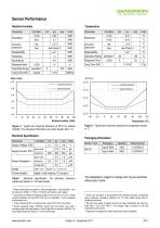
Sensor Performance Relative Humidity1234 Parameter Operating Range extended 4 Response Time Long Term Drift Repeatability Hysteresis Nonlinearity Response time 63% Operating Range extended 4 Long Term Drift 5 normal 3 maximal tolerance typical tolerance ± 2.0 maximal tolerance typical tolerance Figure 2 Typical and maximal tolerance at 25°C for relative humidity. For extensive information see Users Guide, Sect. 1.2. Electrical Specification Parameter Condition Supply Voltage, VDD Heater Communication Figure 3 Typical and maximal tolerance for temperature sensor in °C. Packaging Information sleep...
Open the catalog to page 2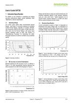
Users Guide SHT20 For details on how Sensirion is specifying and testing accuracy performance please consult Application Note “Statement on Sensor Specification”. Relative Humidity (%) 1.1 Operating Range The sensor works stable within recommended Normal Range – see Figure 4. Long term exposure to conditions outside Normal Range, especially at humidity >80%RH, may temporarily offset the RH signal (+3%RH after 60h). After return into the Normal Range it will slowly return towards calibration state by itself. See Section 2.3 “Reconditioning Procedure” for eliminating the offset. Prolonged exposure...
Open the catalog to page 3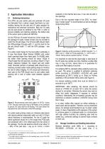
2.1 Soldering Instructions The DFN’s die pad (centre pad) and perimeter I/O pads are fabricated from a planar copper lead-frame by overmolding leaving the die pad and I/O pads exposed for mechanical and electrical connection. Both the I/O pads and die pad should be soldered to the PCB. In order to prevent oxidation and optimize soldering, the bottom side of the sensor pads is plated with Ni/Pd/Au. On the PCB the I/O lands8 should be 0.2mm longer than the package I/O pads. Inward corners may be rounded to match the I/O pad shape. The I/O land width should match the DFN-package I/O-pads width 1:1...
Open the catalog to page 4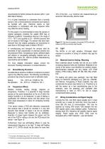
recommended to further process the sensors within 1 year after date of delivery. 10% of the time – e.g. maximum two measurements per second at 12bit accuracy shall be made. It is of great importance to understand that a humidity sensor is not a normal electronic component and needs to be handled with care. Chemical vapors at high concentration in combination with long exposure times may offset the sensor reading. For this reason it is recommended to store the sensors in original packaging including the sealed ESD bag at following conditions: Temperature shall be in the range of 10°C – 50°C and...
Open the catalog to page 5
noted that pull-up resistors may be included in I/O circuits of MCUs. See Table 4 and Table 5 for detailed I/O characteristic of the sensor. 3 Interface Specifications Pin Name Comment 1 SDA Serial Data, bidirectional 4 2 VSS Ground 5 5 VDD Supply Voltage 6 SCL Serial Clock, bidirectional 6 3,4 NC Not Connected Table 2 SHT2x pin assignment, NC remain floating (top view) 3.1 Power Pins (VDD, VSS) The supply voltage of SHT2x must be in the range of 2.1 – 3.6V, recommended supply voltage is 3.0V. Power supply pins Supply Voltage (VDD) and Ground (VSS) must be decoupled with a 100nF capacitor, that...
Open the catalog to page 6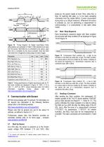
5.2 Start / Stop Sequence Each transmission sequence begins with Start condition (S) and ends with Stop condition (P) as displayed in Figure 13 and Figure 14. Figure 12 Timing Diagram for Digital Input/Output Pads, abbreviations are explained in Table 5. SDA directions are seen from the sensor. Bold SDA line is controlled by the sensor, plain SDA line is controlled by the micro-controller. Note that SDA valid read time is triggered by falling edge of anterior toggle. Parameter SCL frequency, fSCL SCL High Time, tSCLH SCL Low Time, tSCLL SDA Set-Up Time, tSU SDA Hold Time, tHD SDA Valid Time,...
Open the catalog to page 7All Sensirion catalogs and technical brochures
 Antifogging Humidity Sensors
2 Pages
 SDP800/810 Digital
14 Pages
 800/810 Analog
8 Pages
 Liquid Flow Meter LG16
8 Pages
 Liquid Flow Meter LG01
4 Pages
 Liquid Flow Meter LS32-1500
4 Pages
 Liquid Flow Meter SLI
8 Pages
 Liquid Flow Meter SLG
7 Pages
 Liquid Flow Meter SLQ-QT105
6 Pages
 Liquid Flow Meter SLQ-QT500
7 Pages
 Liquid Flow Meter SLS-1500
5 Pages
 Liquid Flow Sensor LPG10
5 Pages
 Liquid Flow Sensor LD20
18 Pages
 Temperature Sensor IC STS21
12 Pages
 STS3x-DIS
18 Pages
 Liquid Flow
5 Pages
 Temperature Sensors
4 Pages
 Humidity Sensors
8 Pages
 Antifogging
2 Pages
 Smart Thermostats
2 Pages
 SHTW2
SHTW214 Pages
 Environmental Sensing
6 Pages
 Datasheet SHTC1
14 Pages
 Datasheet SHT3x digital
21 Pages
 Datasheet SHT3x analog
13 Pages
 LS32-1500
4 Pages
 Liquid Flow Sensor LG16
5 Pages
 Liquid Flow Sensor LG216
6 Pages


- Flowmeter
- Liquid flow monitor
- Resistance temperature sensor
- Waterproof flow meter
- Gas flow monitor
- Industrial flow monitor
- Pressure probe
- Precision flow meter
- In-line flow meter
- Water flow monitor
- Compact flow monitor
- Gas sensor
- DC flow monitor
- RS485 flow monitor
- Mass flow monitor
- Digital flow monitor
- IP65 flow monitor
- Relative humidity and temperature sensor