- Catalogs
- ON Semiconductor
- Quad Analog Switch/Quad Multiplexer
Quad Analog Switch/Quad Multiplexer
1 /11Pages

Quad Analog Switch/Quad Multiplexer
1 /11Pages
Catalog excerpts
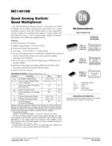
© Semiconductor Components Industries, LLC, 2009 September, 2009 - Rev. 8 1 Publication Order Number: MC14016B/D MC14016B Quad Analog Switch/ Quad Multiplexer The MC14016B quad bilateral switch is constructed with MOS P-channel and N-channel enhancement mode devices in a single monolithic structure. Each MC14016B consists of four independent switches capable of controlling either digital or analog signals. The quad bilateral switch is used in signal gating, chopper, modulator, demodulator and CMOS logic implementation. Features • Diode Protection on All Inputs • Supply Voltage Range = 3.0 Vdc to 18 Vdc • Linearized Transfer Characteristics • Low Noise - 12 nV/ãCycle, f 1.0 kHz typical • Pin-for-Pin Replacements for CD4016B, CD4066B (Note improved transfer characteristic design causes more parasitic coupling capacitance than CD4016) • For Lower RON, Use The HC4016 High-Speed CMOS Device or The MC14066B • This Device Has Inputs and Outputs Which Do Not Have ESD Protection. Antistatic Precautions Must Be Taken. • These are Pb-Free Devices MAXIMUM RATINGS (Voltages Referenced to VSS) Symbol Parameter Value Unit VDD DC Supply Voltage Range -0.5 to +18.0 V Vin, Vout Input or Output Voltage Range (DC or Transient) -0.5 to VDD + 0.5 V Iin Input Current (DC or Transient) per Control Pin ±10 mA ISW Switch Through Current ±25 mA PD Power Dissipation, per Package (Note 1) 500 mW TA Ambient Temperature Range -55 to +125 °C Tstg Storage Temperature Range -65 to +150 °C TL Lead Temperature (8-Second Soldering) 260 °C Stresses exceeding Maximum Ratings may damage the device. Maximum Ratings are stress ratings only. Functional operation above the Recommended Operating Conditions is not implied. Extended exposure to stresses above the Recommended Operating Conditions may affect device reliability. 1. Temperature Derating: Plastic “P and D/DW” Packages: – 7.0 mW/C From 65C To 125C This device contains protection circuitry to guard against damage due to high static voltages or electric fields. However, precautions must be taken to avoid applications of any voltage higher than maximum rated voltages to this high-impedance circuit. For proper operation, Vin and Vout should be constrained to the range VSS (Vin or Vout) VDD. Unused inputs must always be tied to an appropriate logic voltage level (e.g., either VSS or VDD). Unused outputs must be left open. http://onsemi.com MARKING DIAGRAMS 1 14 PDIP-14 P SUFFIX CASE 646 MC14016BCP AWLYYWWG SOIC-14 D SUFFIX CASE 751A 1 14 14016BG AWLYWW A = Assembly Location WL, L = Wafer Lot YY, Y = Year WW, W = Work Week G = Pb-Free Indicator SOEIAJ-14 F SUFFIX CASE 965 1 14 MC14016B ALYWG See detailed ordering and shipping information in the package dimensions section on page 2 of this data sheet. ORDERING INFORMATION
Open the catalog to page 1
MC14016B http://onsemi.com 2 BLOCK DIAGRAM CONTROL 1 IN 1 CONTROL 2 IN 2 CONTROL 3 IN 3 CONTROL 4 IN 4 OUT 1 OUT 2 OUT 3 OUT 4 13 1 5 4 6 8 12 11 2 3 9 10 VDD = PIN 14 VSS = PIN 7 Control Switch 0 = VSS Off 1 = VDD On PIN ASSIGNMENT 11 12 13 14 8 9 5 10 4 3 2 1 7 6 OUT 4 IN 4 CONTROL 4 CONTROL 1 VDD IN 3 OUT 3 IN 2 OUT 2 OUT 1 IN 1 VSS CONTROL 3 CONTROL 2 LOGIC DIAGRAM (1/4 OF DEVICE SHOWN) CONTROL OUT LOGIC DIAGRAM RESTRICTIONS IN VSS Vin VDD VSS Vout VDD ORDERING INFORMATION Device Package Shipping† MC14016BCPG PDIP-14 (Pb-Free) 25 / Tape & Ammo Box MC14016BDG SOIC-14 (Pb-Free) 55 Units / Rail...
Open the catalog to page 2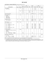
MC14016B http://onsemi.com 3 ÎÎÎÎÎÎÎÎÎÎÎÎÎÎÎÎÎÎÎÎÎÎÎÎÎÎÎÎÎÎÎÎÎ ÎÎÎÎÎÎÎÎÎÎÎÎÎÎÎÎÎÎÎÎÎÎÎÎÎÎÎÎÎÎÎÎÎ ELECTRICAL CHARACTERISTICS (Voltages Referenced to VSS) ÎÎÎÎÎÎÎÎÎÎÎ ÎÎÎÎÎÎÎÎÎÎÎ ÎÎÎÎÎÎÎÎÎÎÎ Characteristic ÎÎÎ ÎÎÎ ÎÎÎ Figure ÎÎÎÎ ÎÎÎÎ ÎÎÎÎ Symbol ÎÎÎ ÎÎÎ ÎÎÎ VDD Vdc ÎÎÎÎ ÎÎÎÎ - 55C ÎÎÎÎÎÎÎÎ ÎÎÎÎÎÎÎÎ 25C ÎÎÎÎ ÎÎÎÎ 125C ÎÎÎ ÎÎÎ ÎÎÎ Unit ÎÎ ÎÎ MinÎÎÎ ÎÎÎ MaxÎÎÎ ÎÎÎ MinÎÎÎÎ ÎÎÎÎ Typ (2) ÎÎÎ ÎÎÎ Max ÎÎ ÎÎ MinÎÎÎ ÎÎÎ Max ÎÎÎÎÎÎÎÎÎÎÎ ÎÎÎÎÎÎÎÎÎÎÎ ÎÎÎÎÎÎÎÎÎÎÎ ÎÎÎÎÎÎÎÎÎÎÎ Input Voltage Control Input ÎÎÎ ÎÎÎ ÎÎÎ ÎÎÎ 1ÎÎÎÎ ÎÎÎÎ ÎÎÎÎ VIL ÎÎÎ ÎÎÎ 5.0 10 15 ÎÎ ÎÎ --- ÎÎÎ ÎÎÎ - - - ÎÎÎ ÎÎÎ - - - ÎÎÎÎ ÎÎÎÎ 1.5...
Open the catalog to page 3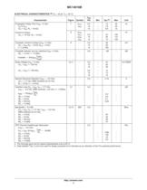
MC14016B http://onsemi.com 4 ÎÎÎÎÎÎÎÎÎÎÎÎÎÎÎÎÎÎÎÎÎÎÎÎÎÎÎÎÎÎÎÎÎ ÎÎÎÎÎÎÎÎÎÎÎÎÎÎÎÎÎÎÎÎÎÎÎÎÎÎÎÎÎÎÎÎÎ ELECTRICAL CHARACTERISTICS (4) (CL = 50 pF, TA = 25C) ÎÎÎÎÎÎÎÎÎÎÎÎÎÎÎÎ ÎÎÎÎÎÎÎÎÎÎÎÎÎÎÎÎ ÎÎÎÎÎÎÎÎÎÎÎÎÎÎÎÎ Characteristic ÎÎÎ ÎÎÎ ÎÎÎ Figure ÎÎÎ ÎÎÎ ÎÎÎ Symbol ÎÎÎÎ ÎÎÎÎ ÎÎÎÎ VDD Vdc ÎÎÎ ÎÎÎ ÎÎÎ Min ÎÎÎÎ ÎÎÎÎ ÎÎÎÎ Typ (5) ÎÎÎ ÎÎÎ ÎÎÎ Max ÎÎÎÎ ÎÎÎÎ ÎÎÎÎ Unit ÎÎÎÎÎÎÎÎÎÎÎÎÎÎÎÎ ÎÎÎÎÎÎÎÎÎÎÎÎÎÎÎÎ ÎÎÎÎÎÎÎÎÎÎÎÎÎÎÎÎ ÎÎÎÎÎÎÎÎÎÎÎÎÎÎÎÎ ÎÎÎÎÎÎÎÎÎÎÎÎÎÎÎÎ Propagation Delay Time (VSS = 0 Vdc) Vin to Vout (VC = VDD, RL = 10 k) Control to Output (Vin 10 Vdc, RL = 10 k) ÎÎÎ ÎÎÎ 7 ÎÎÎ ÎÎÎ tPLH, tPHL ÎÎÎÎ ÎÎÎÎ 5.0 10 15...
Open the catalog to page 4All ON Semiconductor catalogs and technical brochures
 NCV-RSL 15
1 Page
 Networking & Telecom Solutions
28 Pages
 Smart Grid Solutions 2014
16 Pages
 LED Lighting Solutions
48 Pages
 Automotive Products Selector
36 Pages
 White Goods Solutions
32 Pages
 Smart Grid Solutions 2012
12 Pages
 Portable Solutions
28 Pages
 Networking Solutions
24 Pages
 Medical Solutions
16 Pages
 Industrial Solutions
40 Pages
 Image Sensors
12 Pages
 Home Entertainment Solutions
40 Pages
 Computing Solutions
12 Pages
 Automotive Solutions
48 Pages
 1 A Dual H
9 Pages
 Dual 2-Bit Adder / Subtractor
5 Pages


Archived catalogs
 Switching Controllers
20 Pages
 High Power Audio transistors
5 Pages


- Bourn And Koch transceiver
- Motor controller
- Bourn And Koch electronic filter
- Potentiometer
- Bourn And Koch transistor
- Stepper motor controller
- Crystal oscillator
- Rectifier diode
- Bourn And Koch radio transceiver
- Electronic amplifier
- EMI filter
- SMT diode
- Band-pass electronic filter
- Bourn And Koch bipolar transistor
- Digital motor controller
- Active electronic filter
- Surface-mount oscillator
- Light sensor
- DC drive