- Catalogs
- SEM Limited
- TECHNICAL DATA MANUAL ISSUE NO. 5.
TECHNICAL DATA MANUAL ISSUE NO. 5.
1 /100Pages

TECHNICAL DATA MANUAL ISSUE NO. 5.
1 /100Pages
Catalog excerpts
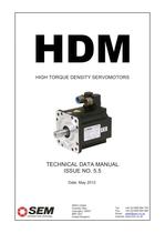
HIGH TORQUE DENSITY SERVOMOTORS TECHNICAL DATA MANUAL ISSUE NO. 5. Date: 201 SEM Limited Faraday Way Orpington, KENT BR5 3QT United Kingdom Tel: +44 (0)1689 884 700 Fax: +44 (0)1689 884 884 Email: [email protected] Internet: www.sem.co.uk
Open the catalog to page 1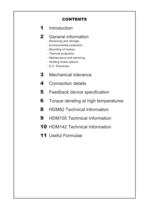
- Environmental protection. - Thermal protection. - Holding brake options 5 Feedback device specification 6 Torque derating at high temperatu
Open the catalog to page 3
INTRODUCTION SEM has continuously developed its range of servo products to best serve the latest industry requirements. The new HDM range of servomotors uses the long experience gained in the servomotor field to give cost effective performance. The HDM range has been specifically designed to provide optimal performance whilst remaining compact and cost effective. The high torque to inertia ratio allows fast acceleration and deceleration and rapid dynamic response. These motors are ideally suited for any high dynamic application where space constraints apply. WHY BRUSHLESS? The optimum performance...
Open the catalog to page 4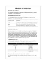
GENERAL INFORMATION On receipt the motors should be inspected. Any damage found should be reported ENVIRONMENTAL PROTECTION All SEM brushless motors are protected to IP65 except at the shaft where the protection is IP64 with a shaft seal fitted. Protection Class Description IP65 Totally protected against dust. Protected against low pressure jets of water from all directions with limited ingress permitted IP64 Totally protected against dust. Protected against water sprayed from all directions with limited ingress permitted Where a toothed belt is proposed, the motors should be flange mounted to...
Open the catalog to page 6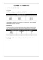
GENERAL INFORMATION MAINTENANCE AND SERVICING BEARINGS All HDM servomotors are fitted with double shielded, single row radial ball bearings. Under normal conditions, no maintenance is required. Bearing Sepcification Frame ISO Code for Drive End ISO Code for Non-Drive End HDM82 6002 2Z 6002 2Z HDM105 6004 2Z 6003 2Z HDM142 6205 2Z 6004 2Z The bearings are selected to give a minimum of 30,000 hours life. Refer to the shaft loading graphs for further information. MECHANICAL It is recommended that a general inspection be made at regular intervals to check all bolts, nuts couplings etc to ensure that...
Open the catalog to page 7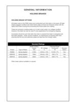
GENERAL INFORMATION HOLDING BRAKES HOLDING BRAKE OPTIONS All brakes used on the HDM motors are constructed such that when in the power off state (brake engaged condition) the brake friction plate is forced into frictional contact with the rigidly fixed brake housing thus preventing the friction plate from rotating. These are primarily a holding brake e.g. to hold a load under a no voltage condition. However, the brake can also be used in some applications for emergency stopping. Connection should be such that when the motor is powered the brake is energized and the brake released. Under normal...
Open the catalog to page 8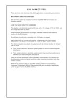
E.U. DIRECTIVES There are three main directives that affect applications incorporating servomotors. MACHINERY DIRECTIVE 2006/42/EC This directive applies to complete machines and SEM HDM servomotors are therefore exempt. LOW VOLTAGE DIRECTIVE 2006/95/EC This applies to all electrical equipment for use with a DC voltage of 75V to 1500V and AC voltage from 50V to 1000V. HDM brushless servomotors in the ranges, HRDM82, HDM105 and HDM142 conform to the EC directive. A certificate of conformity is available from SEM sales on request EMC DIRECTIVE (ELECTRO MAGNETIC COMPATIBILITY) 2004/108/EC The directive...
Open the catalog to page 9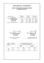
SHAFT EXTENSION RUN-OUT MOUNTING FACE TO SHAFT
Open the catalog to page 10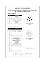
CONNECTION DIAGRAM HDM82 MOTORS FITTED WITH RESOLVER, M23 POWER AND SUPPLY CONNECTOR FEEDBACK CONNECTOR Note that connectors are viewed from customer side
Open the catalog to page 11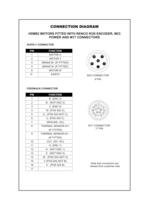
CONNECTION DIAGRAM HDM82 MOTORS FITTED WITH RENCO R35I ENCODER, M23 SUPPLY CONNECTOR FEEDBACK CONNECTOR Note that connectors are viewed from customer side
Open the catalog to page 12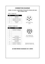
CONNECTION DIAGRAM HDM82, 105 AND 142 MOTORS FITTED WITH RESOLVER AND SUPPLY CONNECTOR FEEDBACK CONNECTOR Note that connectors are viewed from customer side
Open the catalog to page 13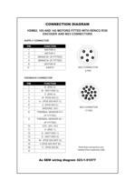
CONNECTION DIAGRAM HDM82, 105 AND 142 MOTORS FITTED WITH RENCO R35I SUPPLY CONNECTOR FEEDBACK CONNECTOR Note that connectors are viewed from customer side
Open the catalog to page 14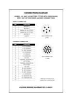
CONNECTION DIAGRAM HDM82, 105 AND 142 MOTORS FITTED WITH HEIDENHAIN SUPPLY CONNECTOR FEEDBACK CONNECTOR Note that connectors are viewed from customer side
Open the catalog to page 15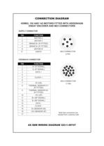
CONNECTION DIAGRAM HDM82, 105 AND 142 MOTORS FITTED WITH HEIDENHAIN ENDAT ENCODER AND M23 CONNECTORS SUPPLY CONNECTOR FEEDBACK CONNECTOR Note that connectors are viewed from customer side
Open the catalog to page 16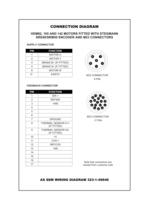
CONNECTION DIAGRAM HDM82, 105 AND 142 MOTORS FITTED WITH STEGMANN SUPPLY CONNECTOR FEEDBACK CONNECTOR Note that connectors are viewed from customer side
Open the catalog to page 17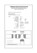
FEEDBACK DEVICE SPECIFICATION SPECIFICATION FOR RESOLVER SIZE 15 Configuration: 2 pole (1 speed), brushless resolver. Input to single phase rotor. Output from 2 phase stator Connections and output equation: see drawing Primary Side Pole Pairs Transformation Ratio Input Voltage Input Current Input Frequency Null Voltage POSITIVE DIRECTION OF ROTATION IS CLOCKWISE LOOKING AT THE DRIVE END OF THE SHAFT
Open the catalog to page 18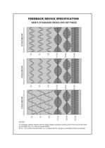
FEEDBACK DEVICE SPECIFICATION Eu Ev Ew S1-S3 S2-S4 R1-R2 Ev Ew S1-S3 S2-S4 R1-R2 R1-R2 S2-S4 S1-S3 Ew Ev Eu 8 POLE MOTOR Rotation clockwise looking at drive end 6 POLE MOTOR Rotation clockwise looking at drive end Eu 10 POLE MOTOR Rotation clockwise looking at drive end SEM’S STANDARD RESOLVER SETTINGS NOTES 1 Clockwise rotation means that the shaft rotates clockwise looking at the drive end of the shaft. 2 The EMFs (Eu, Ev, Ew) are phase EMFs 3 For + VE current into the motor; Iu, in phase with Eu will give a clockwise torque (motoring)
Open the catalog to page 19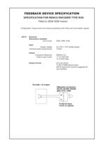
FEEDBACK DEVICE SPECIFICATION SPECIFICATION FOR RENCO ENCODER TYPE R35i Fitted to SEM HDM motors Configuration: Square wave two channel quadrature with index and commutation signals DATA Electrical Resolutions available Line Counts 2048, 4096, 8192 Input Supply voltage Nominal power requirements 5.0 VDC ± 10% Single Supply 175mA Output Frequency Response Output Logic Levels Output Format 500KHz (1x) “1” 2.5 VDC Min “0” 0.5VDC Max LD (Line driver) TI 26C31IDBR typical output 26C32 typical line receiver suggested for user interface
Open the catalog to page 20All SEM Limited catalogs and technical brochures
 Permanent Magnet D.C.Servomotors
65 Pages
 HJ BRUSHLESS AC SERVOMOTORS
144 Pages
 HR / HRS BRUSHLESS AC SERVOMOTORS
212 Pages
 Flyer HW Liquid cooled Issue 2
19 Pages
 Flyer HJ260 Issue 2
1 Page
 Brochure MT
6 Pages
 Brochure HR-HRS
4 Pages
 Brochure HDM
4 Pages
 Brochure HJ
4 Pages
 SEM Overview
1 Page
