SENSE-D01
1 /24Pages

SENSE-D01
1 /24Pages
Catalog excerpts
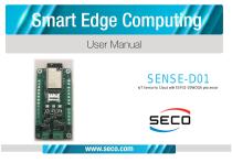
IoT Sensor to Cloud with ESP32-D0WDQ6 processor
Open the catalog to page 1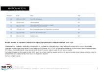
REVISION HISTORY Revision First Official Release. Official Release. Add Others information on Expansion connectors Global review Information added on connectors signal. All rights reserved. All information contained in this manual is proprietary and confidential material of SECO S. p.A. Unauthorized use, duplication, modification or disclosure of the information to a third-party by any means without prior consent of SECO S.p.A. is prohibited. Every effort has been made to ensure the accuracy of this manual. However, SECO S.p.A. accepts no responsibility for any inaccuracies, errors or omissions...
Open the catalog to page 2
SENSE D01 D01 User Manual - Rev. First Edition: 1.0 - Last Edition: 1.5 - Author: LM - Reviewed by SB Copyright © 2020 SECO S.p.A.
Open the catalog to page 3
Warranty Information and assistance RMA number request Safety Electrostatic discharges SENSE D01 D01 User Manual - Rev. First Edition: 1.0 - Last Edition: 1.5 - Author: LM - Reviewed by SB Copyright © 2020 SECO S
Open the catalog to page 4
This product is subject to the Italian Law Decree 24/2002, acting European Directive 1999/44/CE on matters of sale and warranties to consumers. The warranty on this product lasts for 1 year. Under the warranty period, the Supplier guarantees the buyer assistance and service for repairing, replacing or credit of the item, at the Supplier’s own discretion. Shipping costs that apply to non-conforming items or items that need replacement are to be paid by the customer. Items cannot be returned unless previously authorized by the supplier. The authorization is released after completing the specific...
Open the catalog to page 5
What do I have to do if the product is faulty? SECO S.p.A. offers the following services: • • • SECO website: visit http://www.seco.com to receive the latest information on the product. In most cases it is possible to find useful information to solve the problem. SECO Sales Representative: the Sales Rep can help to determine the exact cause of the problem and search for the best solution. SECO Help-Desk: contact SECO Technical Assistance. A technician is at disposal to understand the exact origin of the problem and suggest the correct solution. E-mail: [email protected] Fax (+39) 0575...
Open the catalog to page 6
To request a RMA number, please visit SECO’s web-site. On the home page, please select “RMA Online” and follow the procedure described. A RMA Number will be sent within 1 working day (only for on-line RMA requests). The SENSE D01 board uses only extremely-low voltages. While handling the board, please use extreme caution to avoid any kind of risk or damages to electronic components. Always switch the power off, and unplug the power supply unit, before handling the board and/or connecting cables or other boards. Avoid using metallic components - like paper clips, screws and similar - near the...
Open the catalog to page 7
Introduction Technical specifications Electrical specifications Mechanical specifications Block diagram SENSE D01 D01 User Manual - Rev. First Edition: 1.0 - Last Edition: 1.5 - Author: LM - Reviewed by SB Copyright © 2020 SECO S
Open the catalog to page 8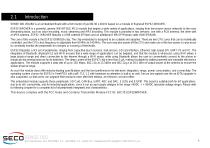
SENSE D01 BOARD is an embedded Board with a form factor of just 86.36 x 40mm based on a module of Espressif ESP32-WROVER. ESP32-WROVER is a powerful, generic WiFi-BT-BLE MCU module that targets a wide variety of applications, ranging from low-power sensor networks to the most demanding tasks, such as voice encoding, music streaming and MP3 decoding. This module is provided in two versions: one with a PCB antenna, the other with an IPEX antenna. ESP32- WROVER features a 4 MB external SPI flash and an additional 8 MB SPI Pseudo static RAM (PSRAM). The core of this module is the ESP32-D0WDQ6 chip....
Open the catalog to page 9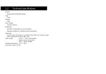
Technical specifications Module Espressif ESP32-WROVER Module Flash 4 MB PSRAM 8 MB Mass Storage microSD Card slot Networking WiFi: 802.11 b/g/n (802.11n up to 150 Mbps) Bluetooth: Bluetooth v4.2 BR/EDR and BLE specification Peripherals SD card, UART, SPI, SDIO, I2C, LED PWM, Motor PWM, I2S, IR, pulse counter, GPIO, capacitive touch sensor, ADC, DAC Power supply: +12VDC ÷ + 24VDC recommended. Minimum Current 1A @ 24Vdc +9VDC ÷ +36VDC absolute Operating temperature: -40°C ÷ +60°C Dimensions: 86.36 x 40
Open the catalog to page 10
Electrical specifications The SENSE D01 board can be supplied with any voltage in the range +9VDC ÷ +36VDC range (absolute voltage range). This voltage can be supplied through a standard a 2-position Terminal Block (P1). Power IN PCB terminal block - P1 Pin
Open the catalog to page 11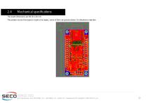
Mechanical specifications The board dimensions are 86.36 x 40 mm. The printed circuit of the board is made of six layers, some of them are ground planes, for disturbance rejection. SENSE D01 D01 User Manual - Rev. First Edition: 1.0 - Last Edition: 1.5 - Author: LM - Reviewed by SB Copyright © 2020 SECO S.p.A.
Open the catalog to page 12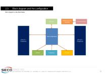
Block diagram and Hw configuration Block diagram is described below. SENSE D01 D01 User Manual - Rev. First Edition: 1.0 - Last Edition: 1.5 - Author: LM - Reviewed by SB Copyright © 2020 SECO S.p.A.
Open the catalog to page 13
Introduction Connectors overview Connectors description SENSE D01 D01 User Manual - Rev. First Edition: 1.0 - Last Edition: 1.5 - Author: LM - Reviewed by SB Copyright © 2020 SECO S.p.A.
Open the catalog to page 14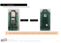
On SENSE D01 board, there are several connectors located on the upper plane. BOTTOM VIEW Please be aware that, depending on the configuration purchased, the appearance of the board could be slightly different from the above pictures. SENSE D01 D01 User Manual - Rev. First Edition: 1.0 - Last Edition: 1.5 - Author: LM - Reviewed by SB Copyright © 2020 SECO S.p.A.
Open the catalog to page 15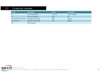
Connectors overview Name UART Connector SENSE D01 D01 User Manual - Rev. First Edition: 1.0 - Last Edition: 1.5 - Author: LM - Reviewed by SB Copyright © 2020 SECO S.p.A.
Open the catalog to page 16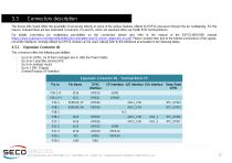
Connectors description The Sense D01 board offers the possibility of accessing directly to some of the various features offered by ESP32 processor through the pin multiplexing. For this reason, onboard there are two dedicated connectors, P3 and P4, which are standard Ultra Low Profile PCB Terminal Blocks. For details concerning pin multiplexing possibilities on the connectors please also refer to the manual of the ESP32-WROVER module (https://www.espressif.com/sites/default/files/documentation/esp32-wrover_datasheet_en.pdf). Please consider that, due to the internal connections of the signals,...
Open the catalog to page 17All SECO catalogs and technical brochures
 DEV-KIT-SMARC
3 Pages
Archived catalogs
 SBC-C57
2 Pages
 ETX-A61
2 Pages
 SECO Products Guide 2021
48 Pages
 SBC-C90
2 Pages
 SM-B69
73 Pages
 SM-B71
2 Pages
 Q7 STARTER KIT 2.0
2 Pages
 SYS-B68-IGW
19 Pages
 COMe-C42-BT7
82 Pages
 SYS-D14-MED
2 Pages
 COMe-B75-CT6
78 Pages
 Flexy Vision 21.5 APL
3 Pages
 COMe-A98-CT6
75 Pages
 SYS-B68-IPC
19 Pages
 μQ7-C72
37 Pages
 μQ7-A76-J
67 Pages
 COMe-C55-CT6
87 Pages
 Q7-C26
45 Pages
 COMe-C24-CT6
76 Pages
 COMe-B09-BT6
77 Pages
 Q7-A36
73 Pages
 COMe-A41-CT6
72 Pages
 SBC-992-pITX
58 Pages
 SBC-A44-pITX
65 Pages
 μQ7-A75-J
40 Pages
 Q7-C25
41 Pages
 SBC-A80-eNUC
63 Pages
 Q7-B03
73 Pages
 SBC-B08
36 Pages
 Q7-928
45 Pages
 SBC-C43
43 Pages
 SBC-984
38 Pages
 SBC-A62-J
39 Pages
 SBC-B68-eNUC
73 Pages
 SBC-C23
34 Pages
 SBC-C31
42 Pages
 SYS-C90-DS
2 Pages
 SYS-A90-IPC
2 Pages
 SBC-C66
2 Pages
 COM EXP T6 DEV KIT
2 Pages
 COM EXP T7 DEV KIT
2 Pages
 Q7 DEV KIT 2.0
2 Pages
 SYS-C23-IGW
2 Pages
 COMe-C89-CT6
2 Pages
 COMe-C08-BT6
2 Pages
 SYS B08-7
2 Pages
 SYS-A62-10
2 Pages
 SM-C12
2 Pages
 μQ7-962
2 Pages
 SBC-C20
2 Pages
 SBC-C41-pITX
2 Pages
 SBC-C61
2 Pages
- LIMING digital camera
- Visible imager
- LIMING CMOS camera
- LIMING industrial camera
- LIMING industrial PC
- LIMING Intel® Core™ PC
- LIMING fanless PC
- LIMING HDMI PC
- LIMING embedded PC
- LIMING box PC
- LIMING RS-232 PC
- LIMING Windows PC
- USB 2.0 PC
- LIMING SATA PC
- LIMING Linux PC
- LIMING USB PC
- LIMING RS-485 PC
- USB 3.0 PC
- LIMING gigabit Ethernet PC
- Compact PC