


COMe-C42-BT7

COMe-C42-BT7
This section outlines the warranty, information and assistance, RMA number request, safety guidelines, electrostatic discharge precautions, RoHS compliance, safety policies, terminology, and reference specifications. It stresses the proprietary nature of the information and prohibits unauthorized use or disclosure.
The document introduces the COMe-C42-BT7 module, detailing its technical and electrical specifications, including power rails and consumption. It provides mechanical specifications and a block diagram to offer a comprehensive understanding of the module's design and functionality.
This section describes various connectors on the module, such as the FAN connector, JTAG connector, SO-DIMM DDR4 slots, BIOS restore switch, and COM Express® Module connectors. Each connector's purpose and specifications are outlined to ensure proper usage and integration.
The BIOS setup section explains the Aptio setup utility, covering the main setup menu, advanced menu, chipset menu, security menu, boot menu, save & exit menu, and event logs menu. It provides detailed instructions on configuring system settings, including AMD CBS, iSCSI, network connections, and more.
The appendices include additional information on thermal design, offering guidelines for maintaining optimal operating temperatures and ensuring system reliability.
The product is covered under the Italian Law Decree 24/2002, aligning with the European Directive 1999/44/CE regarding consumer sales and warranties. The warranty period is one year, with repair, replacement, or credit offered at the supplier's discretion. Customers are responsible for shipping costs for non-conforming or replacement items. Returns require prior authorization via a form on the supplier's website, and items must be returned with all original accessories and packaging.
If the product is faulty, SECO S.p.A. provides several support options: accessing product information on their website, contacting a sales representative, or reaching out to the technical assistance team via email or fax. Faulty products can be sent to the SECO Repair Centre with an RMA number, and items must be properly packaged to avoid damage.
To obtain an RMA number, customers should visit SECO's website and follow the online procedure. An RMA number will be issued within one working day for online requests.
The COMe-C42-BT7 module operates at extremely low voltages and requires careful handling to prevent damage. It is sensitive to electrostatic discharges, and users should ground themselves and use anti-static surfaces when handling the module. The module is RoHS compliant, and users should ensure power is off before handling or connecting components.
The module must be used within a fire enclosure or an appropriate enclosure to meet safety standards. Manufacturers using the module in end-user products must ensure compliance with relevant safety standards and prescribe operating conditions.
The document provides definitions for various technical terms and interfaces relevant to the module, such as ACPI, AHCI, BIOS, and PCI-e.
A list of applicable industry specifications and reference documents is provided, including links to standards for ACPI, AHCI, Com Express, and others.
The module supports various AMD EPYC Embedded processors, up to 128GB of DDR4 memory, multiple USB and Ethernet ports, and PCI-e lanes. It includes interfaces for SPI, I2C, and others, with power supplied at +12VDC.
The COMe-C42-BT7 is a COM Express board with dimensions of 125 x 95 mm. It operates within a temperature range of 0°C to +60°C for the commercial version and -40°C to +85°C for the industrial version. The board requires an external +12VDC power supply and a 5V standby voltage for ATX mode. A backup battery voltage is necessary for the Real Time Clock and CMOS memory data retention.
The board's power consumption is measured using a CCOMe-C79 Carrier board. It requires a carrier board for normal operation, and all connections are made through this board. Power consumption varies based on the CPU and configuration, with specific measurements provided for different states such as idle, boot, and stress test.
The board is a Basic form Factor type with a 12-layer printed circuit for disturbance rejection. It supports up to four SO-DIMM slots for DDR4-2666 memory, with specific height requirements for the carrier board plug to accommodate maximum memory deployment.
The board features two 220-pin connectors (A-B and C-D) for interfacing, a 3-pin or 4-pin FAN connector for cooling, a JTAG connector for testing and debugging, and SO-DIMM slots for memory. The BIOS Restore switch allows resetting to factory defaults if needed.
The block diagram outlines the connections and components on the board, including the AMD EPYC Embedded 3000 Series SoC, DDR4 memory slots, Ethernet controller, and various interfaces such as PCI-e, USB, and SATA.
Users must ensure proper cooling solutions are in place to maintain the heatspreader/heatsink temperature within specified limits. The use of an external fan is application-dependent, and considerations for thermal dissipation are detailed in chapter 5.1 of the manual.
The manual provides detailed pin configurations for connectors CN1 Rows A, B, C, and D, specifying signal types and their respective pin numbers. It includes instructions for connecting Ethernet interfaces directly to an RJ-45 connector on the carrier board.
The module adheres to COM Express Specifications, supporting NC-SI signals for BMC management and 10GBASE-KR interfaces managed by the AMD EPYC Embedded 3000 SoC. It recommends using only necessary differential lanes for FastEthernet and leaving unused pairs unconnected.
- Gigabit Ethernet Signals: Includes MDI differential pairs and activity/link indicators.
- NC-SI Signals: Managed by the Intel® I210 controller, includes clock, data, and arbitration signals.
- 10Gb Ethernet Signals: Managed by the AMD EPYC SoC, includes transmit/receive pairs and I2C management interfaces.
The manual emphasizes the importance of independent analysis and judgment in using the provided schematics, which are offered "AS IS" without warranties. It highlights the need for careful implementation of Ethernet interfaces and adherence to signal management guidelines.
The module uses I2C ports managed by the EPYC Embedded 3000 I2C Port #1/SFP I2C Port. Key signals include 10G_LED_SDA and 10G_LED_SCL for LED and PHY strap data transfer, and interrupt pins (10G_INT0 to 10G_INT3) for xGbE ports, all with 3.3V_ALW signals and 2k2Ω pull-up resistors.
The module supports up to eight S-ATA interfaces, with two available on connector AB, compliant with Gen3 standards supporting data rates of 1.5Gbps, 3.0Gbps, and 6.0Gbps. The document provides details on the differential pairs for transmit and receive channels and mentions the use of 10nF AC series decoupling capacitors.
The module offers 24 PCI Express lanes managed by the AMD EPYC Embedded 3000 SOCs, supporting PCI Express Gen 3 (8.0GT/s). Lanes can be grouped into various configurations via BIOS settings, with a maximum of 7 root ports for lanes #0 to #7 and 8 root ports for lanes #16 to #31.
The module supports USB 2.0 and USB 3.1 Gen1 interfaces, with up to four ports available. USB 2.0 ports support HS, FS, and LS, while USB 3.1 ports provide SuperSpeed capabilities. Overcurrent detection and EMI/ESD protection are emphasized, with specific components and configurations detailed for implementation.
The module provides an LPC interface for managing the embedded microcontroller, with signals such as LPC_AD[0-3], LPC_CLK, LPC_FRAME#, and LPC_SERIRQ. The document outlines the electrical levels and necessary pull-up resistors for these signals.
The module includes a dedicated SPI controller for connecting Serial Flash devices, primarily for BIOS support. Key signals include SPI_CS#, SPI_MISO, and others, with specific electrical levels and pull-up resistor requirements.
The module offers two UART interfaces managed by the embedded controller, with signals such as SER0_TX, SER0_RX, SER1_TX, and SER1_RX at a 3.3V_RUN electrical level. Schottky-diodes are added for +12V tolerance.
Includes signals like WDT, FAN_PWMOUT, FAN_TACHIN, TPM_PP, THRM#, and THRMTRIP#, each with specific voltage levels and functions related to system management and thermal control.
Signals such as PWRBTN#, SYS_RESET#, CB_RESET#, PWR_OK, and various SUS signals manage power states and transitions, with specific voltage levels and pull-up resistors.
Managed by the Embedded Controller, the SMBus interface includes SMB_CK, SMB_DAT, and SMB_ALERT# signals for system management.
There are 8 pins for General Purpose Inputs and Outputs, managed by the embedded microcontroller, with specific electrical levels and resistors.
The setup utility allows configuration of the board using the Aptio Setup Utility stored in onboard SPI Serial Flash. It includes various menus such as Main, Advanced, Chipset, Security, Boot, and Save & Exit.
Includes configuration options for AMD CBS, iSCSI, network connections, battery failure management, trusted computing, ACPI settings, and more.
Submenus for configuring Zen Common Options, Data Fabric, Unified Memory Controller, Northbridge IO, and other AMD-specific settings.
The manual allows for automatic or manual setting of the CLDO_VPP voltage, which requires a system restart to take effect. Fan control can be set to auto or manual, with options to force PWM control and customize fan speed based on temperature thresholds.
Options are available to enable or disable PCIe loopback mode and configure CRS delay and limits. The document also details settings for enabling IOMMU and concurrent training.
SATA and USB configurations can be customized, including enabling/disabling controllers and setting modes. Network settings include iSCSI initiator naming, NIC configuration, and Wake On LAN options.
Security device support can be enabled or disabled, with options for TPM version selection and hierarchy settings. The document also includes settings for ACPI auto configuration and legacy resource locking.
The manual provides detailed options for configuring PCIe lanes, NTB settings, and CPU virtualization. It also includes settings for console redirection, including terminal type and transmission speed.
Other settings include RTC wake options, battery failure management, and trusted computing configurations. The document provides comprehensive options for customizing system behavior and performance.
The document outlines various USB settings including Legacy USB Support, XHCI hand-off, USB Mass Storage Driver Support, and emulation options. It specifies time-out settings for USB transfers and device power-up delays.
Options for enabling or disabling UEFI Network Stack and PXE/HTTP support for both IPv4 and IPv6 are detailed. Configuration policies and boot wait times are also discussed.
This section covers the Compatibility Support Module (CSM) settings, including GateA20 activation, Option ROM messages, INT19 trap responses, and boot option filters for UEFI and Legacy systems.
Device options are dependent on the NVMe and SATA devices present in the system.
Critical and passive cooling temperatures are set, along with thermal constants and sampling periods for passive cooling.
Includes settings for LID_BTN# configuration, SMB_ALERT# wake, hardware monitoring, reset causes, and various fan settings. It also covers watchdog configuration and GPIO settings.
Discusses SMT mode, PCIe link training, and North Bridge information.
Covers secure boot settings, including administrator and user passwords, secure boot modes, and key management options.
The document outlines procedures for configuring Secure Boot, including installing factory default keys, enrolling EFI image files, and managing various certificates and keys such as Platform Key, Key Exchange Keys, and Authorized Signatures. It emphasizes the importance of configuring NVRAM with OEM-defined factory default Secure Boot keys.
The boot menu section provides detailed options for configuring system boot settings. Key options include Setup Prompt Timeout, Bootup NumLock State, Quiet Boot, Fast Boot, SATA Support, VGA Support, USB Support, PS2 Devices Support, Network Stack Driver Support, and Redirection Support. It also covers the selection of boot modes (LEGACY/UEFI) and the system boot order.
This section describes options for saving or discarding changes made in the system setup. Options include Save Changes and Exit, Discard Changes and Exit, Save Changes and Reset, Discard Changes and Reset, and Restore Defaults. It also includes launching the EFI Shell from a filesystem device.
The document details the configuration of SMBIOS Event Log settings, including enabling/disabling event logging, erasing event logs, and managing log behavior when full. It also covers logging system boot events and OEM codes.
The thermal design section emphasizes the importance of effective heat dissipation for the COMe-C42-BT7 module. It discusses the use of heatspreaders and heatsinks, highlighting that the heatspreader is not a standalone cooling solution but a means to transfer heat to other cooling devices. The document advises customers to carefully evaluate and develop cooling solutions based on processor workload, utilization scenarios, and system enclosures.
Catalog excerpts

COMe-C42 BT7 COM-Express Type 7 Module with the AMD EPYC Embedded 3000 Series of SoCs.
Open the catalog to page 1
REVISION HISTORY Revision 1.0 First Official Release All rights reserved. All information contained in this manual is proprietary and confidential material of SECO S.p.A. Unauthorised use, duplication, modification or disclosure of the information to a third-party by any means without prior consent of SECO S.p.A. is prohibited. Every effort has been made to ensure the accuracy of this manual. However, SECO S.p.A. accepts no responsibility for any inaccuracies, errors or omissions herein. SECO S.p.A. reserves the right to change precise specifications without prior notice to supply the best product...
Open the catalog to page 2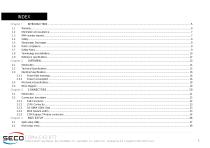
COMe-C42-BT7 COMe-C42-BT7 User Manual - Rev. First Edition: 1.0 - Last Edition: 1.0 - Author: S.B. - Reviewed by E.S. Copyright © 2021 SECO S.p.A.
Open the catalog to page 3
COMe-C42-BT7 COMe-C42-BT7 User Manual - Rev. First Edition: 1.0 - Last Edition: 1.0 - Author: S.B. - Reviewed by E.S. Copyright © 2021 SECO S.p.A.
Open the catalog to page 4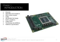
Warranty Information and assistance RMA number request Safety Electrostatic Discharges RoHS compliance Safety Police Terminology and definitions Reference specifications COMe-C42-BT7 COMe-C42-BT7 User Manual - Rev. First Edition: 1.0 - Last Edition: 1.0 - Author: S.B. - Reviewed by E.S. Copyright © 202
Open the catalog to page 5
1.1 Warranty This product is subject to the Italian Law Decree 24/2002, acting European Directive 1999/44/CE on matters of sale and warranties to consumers. The warranty on this product lasts 1 year. Under the warranty period, the Supplier guarantees the buyer assistance and service for repairing, replacing or credit of the item, at the Supplier’s own discretion. Shipping costs that apply to non-conforming items or items that need replacement are to be paid by the customer. Items cannot be returned unless previously authorised by the supplier. The authorisation is released after completing the...
Open the catalog to page 6
1.2 Information and assistance What do I have to do if the product is faulty? SECO S.p.A. offers the following services: • • • SECO website: visit http://www.seco.com to receive the latest information on the product. In most cases it is possible to find useful information to solve the problem. SECO Sales Representative: the Sales Rep can help to determine the exact cause of the problem and search for the best solution. SECO Help-Desk: contact SECO Technical Assistance. A technician is at disposal to understand the exact origin of the problem and suggest the correct solution. E-mail: [email protected]...
Open the catalog to page 7
The COMe-C42-BT7 module uses only extremely-low voltages. While handling the board, please use extreme caution to avoid any kind of risk or damages to electronic components. Always switch the power off, and unplug the power supply unit, before handling the board and/or connecting cables or other boards. Avoid using metallic components - like paper clips, screws and similar - near the board when connected to a power supply, to avoid short circuits due to unwanted contacts with other board components. If the board has become wet, never connect it to any external power supply unit or battery. Check...
Open the catalog to page 8
1.7 Safety Police In order to meet the safety requirements of EN62368-1:2014 standard for Audio/Video, information and communication technology equipment, the COMe-C42 Module shall be: - used inside a fire enclosure made of non-combustible material or V-1 material (the fire enclosure is not necessary if the maximum power supplied to the module never exceeds 100 W, even in worst-case fault); used inside an enclosure; the enclosure is not necessary if the temperature of the parts likely to be touched never exceeds 70 °C; installed inside an enclosure compliant with all applicable IEC 62368-1 requirements;...
Open the catalog to page 9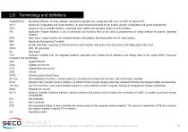
1.8 Terminology and definitions 10GBASE-KR ACPI AHCI API Backplane Ethernet, 10 Gbps datarate, designed to operate over a single lane with up to 1m (39”) of copper PCB. Advanced Configuration and Power Interface, an open industrial standard for the board’s devices configuration and power management Advanced Host Controller Interface, a standard which defines the operation modes of SATA interface Application Program Interface, a set of commands and functions that can be used by programmers for writing software for specific Operating Systems BIOS Basic Input / Output System, the Firmware Interface...
Open the catalog to page 10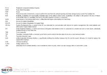
PCI-e PWM PWR PXE RAS SATA SEV SEV-ES SM Bus SPI TBM TLB TTL UEFI USB V_REF xHCI Peripheral Component Interface Express Pulse Width Modulation Power Preboot Execution Environment, a way to perform the boot from the network ignoring local data storage devices and/or the installed OS Reliability, Availability and Serviceability. Reliability refers to the ability to detect errors. Availability is the ability to still operate in the face of failure. Serviceability refers to capabilities that reduce the effort required to service a component. Serial Advance Technology Attachment, a differential half...
Open the catalog to page 11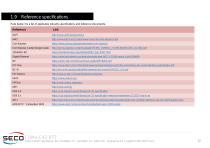
1.9 Reference specifications Here below it is a list of applicable industry specifications and reference documents. Com Express Carrier Design Guide Gigabit Ethernet COMe-C42-BT7 COMe-C42-BT7 User Manual - Rev. First Edition: 1.0 - Last Edition: 1.0 - Author: S.B. - Reviewed by E.S. Copyright © 2021 SECO S.p.A.
Open the catalog to page 12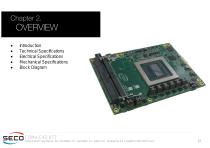
Introduction Technical Specifications Electrical Specifications Mechanical Specifications Block Diagram COMe-C42-BT7 COMe-C42-BT7 User Manual - Rev. First Edition: 1.0 - Last Edition: 1.0 - Author: S.B. - Reviewed by E.S. Copyright © 2021 SECO S.
Open the catalog to page 13
2.1 Introduction The COMe-C42-BT7 is a COM Express® Type 7, basic Form Factor, based on the AMD EPYC Embedded 3000 3000 processors, specifically targeted for networking/server applications. The complete list of processors is available in the next chapter. The main features of this new processor are I/O integration, flexibility, and security capabilities, scalable offering, harnessing the power of the new “Zen” CPU architecture. Moreover, the performance is enhanced by the four DDR4 SO-DIMM slots supporting DDR4-2666 memory with ECC, up to 128GB. This innovative solution provides scalable offerings...
Open the catalog to page 14All SECO catalogs and technical brochures
 DEV-KIT-SMARC
3 Pages
Archived catalogs
 SBC-C57
2 Pages
 ETX-A61
2 Pages
 SECO Products Guide 2021
48 Pages
 SBC-C90
2 Pages
 SM-B69
73 Pages
 SM-B71
2 Pages
 Q7 STARTER KIT 2.0
2 Pages
 SYS-B68-IGW
19 Pages
 SYS-D14-MED
2 Pages
 COMe-B75-CT6
78 Pages
 Flexy Vision 21.5 APL
3 Pages
 COMe-A98-CT6
75 Pages
 SENSE-D01
24 Pages
 SYS-B68-IPC
19 Pages
 μQ7-C72
37 Pages
 μQ7-A76-J
67 Pages
 COMe-C55-CT6
87 Pages
 Q7-C26
45 Pages
 COMe-C24-CT6
76 Pages
 COMe-B09-BT6
77 Pages
 Q7-A36
73 Pages
 COMe-A41-CT6
72 Pages
 SBC-992-pITX
58 Pages
 SBC-A44-pITX
65 Pages
 μQ7-A75-J
40 Pages
 Q7-C25
41 Pages
 SBC-A80-eNUC
63 Pages
 Q7-B03
73 Pages
 SBC-B08
36 Pages
 Q7-928
45 Pages
 SBC-C43
43 Pages
 SBC-984
38 Pages
 SBC-A62-J
39 Pages
 SBC-B68-eNUC
73 Pages
 SBC-C23
34 Pages
 SBC-C31
42 Pages
 SYS-C90-DS
2 Pages
 SYS-A90-IPC
2 Pages
 SBC-C66
2 Pages
 COM EXP T6 DEV KIT
2 Pages
 COM EXP T7 DEV KIT
2 Pages
 Q7 DEV KIT 2.0
2 Pages
 SYS-C23-IGW
2 Pages
 COMe-C89-CT6
2 Pages
 COMe-C08-BT6
2 Pages
 SYS B08-7
2 Pages
 SYS-A62-10
2 Pages
 SM-C12
2 Pages
 μQ7-962
2 Pages
 SBC-C20
2 Pages
 SBC-C41-pITX
2 Pages
 SBC-C61
2 Pages
- Digital imager
- Visible imager
- CMOS camera module
- Industrial camera module
- SECO Intel® Core™ PC
- SECO industrial PC
- SECO fanless PC
- SECO HDMI PC
- SECO embedded PC
- SECO box PC
- SECO RS-232 PC
- SECO USB 2.0 PC
- SECO Windows PC
- SECO SATA PC
- SECO Linux PC
- SECO USB PC
- SECO RS-485 PC
- SECO USB 3.0 PC
- SECO gigabit Ethernet PC
- Compact PC