
- Catalogs
- SECO TOOLS
- Double Octomill? R220.48


Double Octomill? R220.48

Double Octomill? R220.48
This section covers edge preparation techniques for finishing pearlitic grey cast iron, focusing on honed and chamfered edges and specific geometries for high feed applications.
Details on various CBN inserts, including specifications for chamfer size and angle, are provided. Solid CBN inserts like CBN050C and CBN060K are described with dimensions and applications.
A new method called Plunge Turning is introduced, offering significant reductions in cutting time and improved surface integrity compared to conventional hard turning. General cutting data recommendations are included.
Guidelines on the maximum depth of cut for different insert types and grades are provided, emphasizing the importance of tool cutting edge angles.
Various Secomax PCBN grades, both coated and uncoated, are outlined with their application areas. Specific grades like CBN050C and CBN060K are detailed with intended uses and characteristics.
Recommendations for cutting data are provided for various materials, including case-hardened steel, hardened steel, manganese steel, and pearlitic cast iron. Each material type includes basic conditions and preferred CBN grades for different machining operations.
Information on toolholders for external turning and cartridges is provided, including dimensions and spare parts. Specific toolholder models and their compatibility with different inserts are detailed.
The document lists toolholders compatible with inserts LCGF, LCGN, LCMF, and LCMR, specifying dimensions such as height, width, and length, along with required clamp screws, keys, and torque values. The toolholders are categorized by internal and external applications, with specific part numbers for each type.
Details on spare parts and accessories, including clamp screws, keys, and coolant adapters, are provided. The document emphasizes checking availability in the current price and stock list, noting that some accessories must be ordered separately.
Information on modular blades for inserts is included, with dimensions and part numbers. The document outlines the maximum depth of cut for different insert types and provides guidelines for initial plunge dimensions.
The document details various inserts, including part numbers, grades, and tolerances. It specifies dimensions such as cutting edge distance, thickness, and corner radius. Inserts are available in both coated and uncoated versions, with stock standards indicated.
Instructions for assembling toolholders and blades are referenced, with page numbers provided for detailed guidance. Users are advised to verify component compatibility and adhere to specified torque values to ensure proper assembly and function.
The document lists toolholders with part numbers such as 2525M03R080055-JET, detailing dimensions like seat size, height, width, length, and other parameters. These specifications are crucial for selecting the appropriate toolholder for specific machining tasks.
The document outlines initial plunge dimensions related to face groove diameter and provides guidance on selecting right-hand or left-hand versions based on blade orientation. It also specifies the maximum depth of cut for certain inserts.
Recommendations include checking the availability of parts in the current price and stock list. The document advises on correct torque values for clamp screws and key plugs, essential for ensuring secure attachment of toolholders and inserts.
Tables provide a comprehensive list of toolholder dimensions and corresponding torque values. For example, toolholders with dimensions ..03.. require a torque value of 6.0 Nm, while those with dimensions ..06.. require 10.0 Nm.
These toolholders are designed for use with inserts such as LCGF, LCGN, LCMF, and LCMR, detailed on specific pages of the document. Applications are primarily in external axial machining operations.
The document provides detailed technical specifications and guidelines for various toolholders, inserts, and milling cutters used in machining operations. It includes information on spare parts, dimensions, and recommended cutting parameters for different materials.
The document lists various toolholders for S-inserts and Snap Tap, specifying types of anvils, screws, and clamps required. It also provides part numbers and dimensions for different toolholder models, emphasizing the need to check availability in current price and stock lists.
Specifications for Seco-Capto™ adapters for shank tools are detailed, including part numbers and dimensions. The document highlights the importance of ordering certain components separately.
The document explains the code key system used by Seco for milling cutters, which includes designations for cutter diameter, number of teeth, and other features. It provides examples of different cutter systems and their specific code keys.
Various cutter geometries are described, including major cutting edge angles and rake angles. The document outlines different insert clamping systems, such as screw clamping, wedge clamping, and spring action clamping.
Detailed specifications for face milling operations are provided, including spare parts, dimensions, and recommended cutting data. The document includes tables with cutting speeds, feed rates, and depth of cuts for different materials, emphasizing the importance of coolant to manage heat during machining.
The document offers cutting data for full engagement width, specifying surface finish and recommended feed rates for various material groups. It provides guidance on selecting the appropriate insert and cutting parameters based on material type and desired outcomes.
This technical document serves as a comprehensive guide for selecting and using toolholders, inserts, and milling cutters in machining operations. It emphasizes the importance of adhering to specified dimensions, cutting parameters, and clamping systems to achieve optimal performance and tool life.
The document provides detailed technical specifications and recommendations for milling operations using helical milling cutters. It includes data on cutting speeds, feed rates, and insert selections for various material groups and engagement widths.
- Full Engagement (ae/Dc = 100%): Recommended feed rates range from 0.06 to 0.18 mm/tooth. Speed factors and chip thickness are provided for different operations.
- Side Milling: Engagement percentages of 25%, 10%, and 5% are detailed with corresponding feed rates and speed factors.
- For full engagement, multiply the speed value from basic cutting data by the speed factor to determine the suitable feed.
- Side milling operations require adjustments based on the percentage of engagement and the material group.
- Universal inserts such as XOMX 090308TR-M08 MP2500 are recommended for slotting and contouring.
- Specific inserts are suggested for different material groups and operations, with alternatives for difficult operations.
- Tables provide cutting speeds (vc) and feed rates (fz) for various material groups and grades.
- Data is segmented by engagement width, with specific recommendations for full and partial engagements.
- Choose suitable feed rates based on material group and operation type.
- Consider speed factors and chip thickness when planning milling operations.
- Average chip thickness (hm) is specified for different operations.
- Speed factors vary based on the type of milling and engagement percentage.
The document provides detailed specifications and guidelines for disc milling cutters, including types, dimensions, and assembly instructions. It covers various cutter types, insert selections, and spare parts availability.
The document lists different types of disc milling cutters, such as Type A and Type B, with specific dimensions and part numbers. It includes details on cutter diameters, widths, and tool angles. The cutters are categorized by their application, such as milling arbor or stub arbor, and whether they have fixed or adjustable pockets.
Instructions for selecting inserts and cutting data recommendations are provided, with references to specific pages for more detailed information. The document also outlines the assembly alternatives and standard parts required for different cutter types, including assembly screws and keys.
The document advises checking the availability of parts in the current price and stock list. It also provides guidelines for ordering drive rings and keys separately. Recommendations for insert selection and cutting data are referenced to specific pages in the catalogue.
The tables in the document provide dimensions in millimeters for various cutter parts, including diameter, length, and effective number of teeth. They also list part numbers for holders and drive rings, along with their corresponding dimensions.
The document emphasizes the importance of checking part availability and ordering keys separately. It also highlights the need to refer to specific pages for complete insert programs and spare parts information.
The document provides detailed specifications and guidelines for the use of various grades of cutting tools in milling operations. It includes data on feed rates, cutting speeds, and recommended insert types for different material groups.
- Material Groups and Grades: The document categorizes materials into groups and specifies compatible grades such as MP1500, MP2500, MP3000, T350M, F40M, MK1500, and H25.
- Feed Rates (fz): Feed rates are provided in mm/tooth, ranging from 0.03 to 0.25 depending on the material group and operation type.
- Cutting Speeds (vc): Cutting speeds are specified in m/min, with values varying based on the material group and grade, ranging from 35 to 1240 m/min.
- Radial Infeed and Side Milling: The document outlines recommended feed rates and speed factors for radial infeed and side milling operations, with specific values for different percentages of engagement width (ae/Dc).
- Insert Selection: Recommendations for insert types are provided for each material group, with first choice and alternative options listed.
- Universal Inserts: The document suggests universal inserts such as LNK..-M06 F40M and RDHT 06T1M0-E02 F40M for various operations.
- Disc Milling Cutters: Specific cutting data is provided for disc milling cutters, including engagement width and type of insert.
- Feed and Speed Data: Tables provide detailed feed and speed data for different material groups and grades, highlighting the optimal parameters for efficient milling operations.
- Insert Types and Alternatives: Tables list recommended insert types for each material group, with alternatives for flexibility in tool selection.
- Exigencies: The document emphasizes the importance of selecting the correct feed rate and cutting speed to ensure optimal tool performance and material finish.
- Limitations: Some operations have specific limitations on feed rates and cutting speeds, which are crucial for preventing tool wear and ensuring safety.
The document provides a comprehensive guide on various types of EPB holders, focusing on Axiaset™ shell mill holders, side lock holders, and Shrinkfit holders. It details specifications, assembly instructions, and maintenance guidelines for each type, emphasizing their applications in multi-spindle machining centers and face milling operations.
These holders are designed for multi-spindle productivity, allowing for the simultaneous operation of multiple spindles. The Axiaset™ system includes a two-part assembly with a front shell mill holder and a back spindle taper. Key features include a length adjustment capacity of 3 mm, a direct run-out of 20 μm, and a coolant supply through multi-channels. The document provides detailed assembly and length setting instructions, emphasizing the importance of precise adjustments for optimal performance.
The document describes Weldon short side lock holders, highlighting their compatibility with DIN 1835-1 Form B/ISO 5414-1 standards. These holders offer a direct run-out of 5 μm and are available in various bore sizes. The guide includes specifications for different taper types and balancing options, ensuring maximum rigidity and precision in machining operations.
The new Shrinkfit holders type 5603 replace the previous type 5803, featuring a new internal thread for stop end screws and additional balancing threaded holes. These holders conform to DIN 69882-8 standards and offer a run-out of 3 μm at 3xd maximum. The document outlines the transmittable torque capacities and maximum RPM for different clamp diameters, providing guidelines for balancing and tool length setting using Easyshrink® accessories.
The document lists various accessories and spare parts for each holder type, including balancing screws, stop end screws, and setting adapters. It emphasizes the importance of using compatible components to maintain the performance and longevity of the holders.
The guide serves as a detailed reference for selecting and using EPB holders in machining applications, providing essential information on specifications, assembly procedures, and maintenance practices to enhance productivity and precision.
Shrinkfit Holders
Type BM5603 and 5603 Shrinkfit holders are available in DIN type Graflex® and Seco-Capto™. For extensions, refer to the current Tooling Systems catalogue. Availability should be checked in the current price and stock-list. These holders do not have fine-tune balancing threaded holes.
These tool holders are available in various sizes (C3, C4, C5, C6, C8) with different dimensions and balancing specifications. The table provides detailed measurements for each size, including shank diameter, part number, and other critical dimensions.
New ER collet chucks type 5675 replace the previous type 5875, offering improved run-out quality of 10 μm maximum. The clamping range is up to 1 mm, conforming to ISO 15488 standards. The document details the recommended tightening torque for locking nuts across different sizes (ER16, ER25, ER32, ER40).
Available in HSK-A, HSK-E, DIN 69871, and BT JIS standards, these holders have specific dimensions and balancing requirements. The document lists part numbers, sizes, and dimensions for each type.
Details on spanners, sealing nuts, sealing rings, nuts, and stop end screws are provided for various ER sizes. Availability should be checked in the current price and stock-list.
New additions include Combimaster M6 size arbors, extensions, and reducers. The recommended tightening torque for M06 connections is specified.
This document provides comprehensive specifications and guidelines for various tool holders and accessories, emphasizing the importance of checking current availability and stock lists for precise planning and procurement.
The boring head features an indirect barrel locking mechanism, ensuring that the barrel locking screw does not affect the set diameter. The procedure involves unlocking the barrel locking screw, adjusting the diameter using the micrometric adjusting screw, and then tightening the locking screw to secure the barrel in place. The setting dial allows for precision adjustments with increments of 0.01 mm, and the vernier fine adjustment offers a resolution of 2.5 μm. Adjustments are made clockwise to increase the diameter and counterclockwise to decrease it. For optimal precision, it is recommended to preset the head at a smaller diameter, perform a test bore, and then adjust to the required diameter.
The head is designed for reliable settings, particularly when adjusting clockwise to increase the diameter. For reducing the diameter, a preliminary counterclockwise adjustment followed by a clockwise setting is advised for reliability.
The document provides a table of maximum RPM and cutting speeds for various boring kits, emphasizing that these limits are based on the mechanical design and balancing quality of the boring head. It is crucial to select speeds within these limits considering other machining conditions.
The axial fine boring kit covers a range from 10 to 32 mm with a single head and three tools. It offers precise micrometric adjustments and is dust-proof and lubricated for life. The kit includes a protective case and is compatible with a single insert size for all boring bars.
The document details various additional equipment and accessories, including sealing rings for D type sealing nuts, ER collets with improved run-out quality, and Shrinkfit devices for heating, cooling, and height setting. The Easyshrink® 20 Select pack is highlighted as a comprehensive solution for Shrinkfit operations.
For troubleshooting, users are directed to the current Holemaking catalogue, specifically the Axiabore® chapter.
Various toolholder support boxes are described, including three-station and six-station configurations. The dimensions for each type are provided, with specifications for both rotary and non-rotary support boxes, some with height settings and pneumatic tool ejection activators. The toolholders are compatible with SA50/HSK-A100 tapers.
Details on shrinkfit holders and tool shank sizes are provided, including depth comparators and rulers for stop rod setting, with specific depth capacities. Tool supporting sleeves and stop end screw setting adapters are also listed with their respective dimensions.
The document classifies workpiece materials into groups based on their mechanical properties, such as tensile strength (Rm) and cutting force coefficient (kc1.1). It includes classifications for steels, stainless steels, cast iron, and other materials like non-ferrous metals and superalloys. Each material group is associated with specific machining parameters.
Further classification of workpiece materials is provided, detailing various standards and specifications across different international systems (AISI, DIN, BS, AFNOR, etc.). This section includes detailed information on the chemical composition and mechanical properties of different steel and stainless steel grades, as well as cast iron types.
- Toolholder support boxes are available in multiple configurations, with specific dimensions and features for different machining needs.
- Shrinkfit devices and accessories are detailed for precise tool setting and support.
- Comprehensive classification of workpiece materials aids in selecting appropriate machining parameters based on material properties.
- International standards for material classification are provided, facilitating global compatibility and understanding.
The document lists various material grades such as GG-30, GGG-70, and others, along with their corresponding codes and specifications. These grades are likely related to different types of metals and alloys used in manufacturing and engineering applications.
The document provides a detailed table of machinability percentages for various nickel-base, titanium, iron-base, cobalt alloys, and precipitation-hardened stainless steel. Lower percentages indicate higher machining difficulty. For example, Astroloy has a machinability of 14%, while Nickel 201 has 60%.
Seco Tools declares that their cemented carbide inserts, CBN and PCD inserts, cermet inserts, black oxide insert carriers, and nickel-coated insert carriers comply with RoHS, WEEE, and ELV requirements. The document emphasizes the absence of hazardous substances like mercury and lead in concentrations exceeding regulatory specifications.
The document advises on safety precautions during regrinding to prevent exposure to hazardous dusts. It also outlines disposal and recycling procedures for used inserts and carriers, emphasizing the separation of different metal wastes and the recyclability of packing materials.
Special attention is given to nickel leaching from cermet inserts and nickel-coated carriers, advising protective measures for individuals with nickel allergies. Seco Tools is working on processes to meet environmental standards for nickel leaching.
A table lists the presence of various alloying elements like W, Ti, Co, and others in different cemented carbide grades, indicating their composition and potential applications.
Catalog excerpts

Contents Turning Technical information, ISO Turning . . . . . . . . . . . . . . . . . . . . Technical information, PCBN . . . . . . . . . . . . . . . . . . . . . . . . . 4 - 10 11 - 22 ISO Turning Toolholders. . . . . . . . . . . . . . . . . . . . . . . . . . . . . . . . . . . . . . . Inserts. . . . . . . . . . . . . . . . . . . . . . . . . . . . . . . . . . . . . . . . . . . Inserts, Secomax – PCBN . . . . . . . . . . . . . . . . . . . . . . . . . . . 23 - 24 25 - 63 64 - 95 MDT Technical information . . . . . . . . . . . . . . . . . . . . . . . . . . . . . . . Toolholders, external . . . ....
Open the catalog to page 2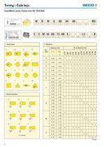
Turning - Code keys Insert/Metric series, Extract from ISO 1832-2004
Open the catalog to page 4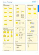
Turning - Code keys 4. Fixing and/or chipbreaker 5. Cutting edge length LF = full-face Insert (sintered layer) nose radius •Metric version round Inserts 8. Cutting edge condition W = High feed Inserts
Open the catalog to page 5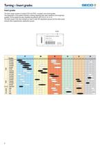
Turning - Insert grades Insert grades The Seco range consists of coated (CVD and PVD), uncoated, and cermet grades. The designation of the grades indicates a ranking regarding their wear resistance and toughness qualities. All the grades are also classified according to ISO (R M, K, N, S, H). The black areas In the chart indicate an insert's main ISO application groups and the white areas Indicate other supplementary application groups.
Open the catalog to page 6
Turning - Insert grades Intended for medium-roughing and roughing of steel and alloyed steel requiring a very high degree of heat and wear resistance. Intended for general turning of steel and alloyed steel. The high wear resistance offers high speed capability TP2500 is Intended for a wide range of turning applications In both steel and stainless steel and Is also a good choice for cast Iron. The wear resistance and edge strength together with the high versatility make the grade the first choice In a large number of applications. Intended for rough or Intermittent turning In steels and stainless...
Open the catalog to page 7
Turning - Insert grades
Open the catalog to page 8
Turning - Insert grades Avery hard PVD-coated super fine grained grade intended for machining of steel components with both hardened and soft areas. The superior edge toughness provides excellent performance In Interrupted cuts in hardened steels as well as In hard surface removal. Nanolaminate based on TI-AI-SI-N Hard micrograin principally Intended for finishing operations in superalloys and titanium alloys. Also per- forms well In finishing operations on stainless steel. Tougher alternative to TS2000. TS2500 Is principally Intended for roughing operations in superalloys and titanium alloys....
Open the catalog to page 9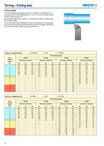
Turning - Cutting data Cutting speed The recommended cutting speeds (m/min) in the tables are estimated for 15 minutes tool life for Seco material groups 1-7 and 12-15, and 10 minutes tool life for Seco material groups 8-11. Use the tables beginning on page 501 to classify the workplece material into a Seco material group. For more accurate recommendations with other combinations of cutting depths and nose radius and other feed rates than those used In the tables, use the Se- color Turning calculator, please see www.secotools.com.
Open the catalog to page 10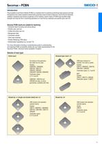
Secomax – PCBN Introduction Polycrystalline Cubic Boron Nitride (PCBN) is a material which is sintered at extremely high pressure and high temperature into a wear-resistant material with properties close to those of diamond. Due to the hot hardness, oxidation resistance and fracture toughness of the material, inserts made of PCBN have excellent edge strength and long tool life in machining operations on hard ferrous materials and pearlitic grey cast iron. Secomax PCBN inserts are suitable for machining: • Hardened steel (including hard-facing alloys) • Pearlitic grey cast iron • Chilled and white...
Open the catalog to page 11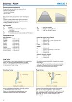
Secomax - PCBN Geometry recommendations Strong cutting edge geometries are always preferred. • Negative cutting geometry • Chamfered cutting edge Sharp positive cutting edge geometry can be advantageous • Finishing of small hardened bores without Interruptions • Finishing of unstable components without interruptions • Finishing of pearlitlc grey cast iron Edge preparation E25 = Extra honed, Intended for Nickel-based S25 = Chamfered and extra honed Intended for PM material Chamfer size and angle Plunge Turning The vast majority of heat treated components in the metalworklng industry are machined...
Open the catalog to page 12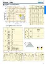
Secomax - PCBN Maximum depth of cut recommendations Round inserts The tool cutting edge angle Is limited to 75° resulting In maximum True tip length (TTL) in mm per nose radius (rs) and tip type
Open the catalog to page 13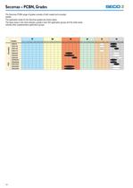
Secomax - PCBN, Grades The Secomax PCBN range of grades consists of both coated and uncoated The application areas for the Secomax grades are shown below. The black areas In the chart Indicate a grade's main ISO application groups and the white areas Indicate other supplementary application groups.
Open the catalog to page 14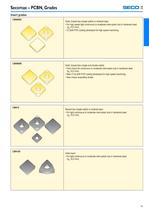
Secomax - PCBN, Grades Insert grades Solid, brazed tips (single sided) or sintered layer • For high speed light continuous to moderate interrupted cuts In hardened steel • (TI,Si)N PVD coating developed for high speed machining. Solid, brazed tips (single and double sided) • First choice for continuous to moderate Interrupted cuts in hardened steel • New (Ti,SI,AI)N PVD coating developed for high speed machining. • New unique superalloy binder. Brazed tips (single sided) or sintered layer • For light continuous to moderate interrupted cuts In hardened steel
Open the catalog to page 15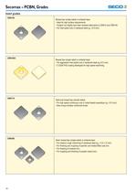
Secomax - PCBN, Grades Insert grades Brazed tips (single sided) or sintered layer • Ideal for high surface requirements. • Tougher but slightly less wear resistant alternative to CBN 10 and CBN 100. • For Interrupted cuts in hardened steel (ap <0,5 mm). Brazed tips (single sided) or sintered layer • For aggressive Interrupted cuts in hardened steel (ap<0,5 mm). • (Ti,SI)N PVD coating developed for high speed machining. Solid and brazed tips (double sided) • For high speed continuous cuts in nickel based superalloys (ap <0,5 mm). • New unique whisker reinforced binder. Solid, brazed tips (single...
Open the catalog to page 16All SECO TOOLS catalogs and technical brochures
 KIT_CATALOG_GT24-100
24 Pages
 DigitalTransition 2024
10 Pages
 TURBO 16
6 Pages
 DOUBLE QUATTROMILL™ 14
70 Pages
 SECO NEWS 2019.1
16 Pages

Archived catalogs
 SECO NEW TOOLING & EXPANSIONS
64 Pages
 MILLING
752 Pages
 HIGHFEED 4 LO06
21 Pages
 Seco X4
2 Pages
 MN 2012 Threading (4 Mb)
126 Pages
 MN 2012 Turning
652 Pages
 MN 2012 Holemaking (22 Mb)
499 Pages
 MN 2012 Update
116 Pages
 Advanced Cutting Materials
55 Pages
 MN 2014 Update 1
164 Pages
 TS2000 & TS2500
20 Pages
 Duratomic® TM2000 and TM4000
20 Pages
 HIGHFEED 2 LP05
22 Pages
 Update 2013-2
298 Pages
 MN 2012 Tooling (21 Mb)
422 Pages
 MN 2012 Solid End Mills (17 Mb)
298 Pages
 Jabro? Composite cutters
55 Pages
 VHM Conventional Tools
56 Pages
 Diamond Coated Tools
13 Pages
 MN 2014 Milling
675 Pages
 Mini - Miniature Tools
15 Pages
 Jabro? JHP 770 & JHP 780
2 Pages
 Jabro-Solid²
4 Pages
 Quattromill Alu
2 Pages
 Disc Milling brochure
36 Pages
 MM4500
2 Pages
 NEW MILLING GRADES 2008
16 Pages
 Tooling
358 Pages
 TTP2050 – NEW THREADING GRADE
14 Pages
 GL25-HEADS RANGE EXPANSION
13 Pages
 TOOLING
14 Pages
 CATALOG & TECHNICAL GUIDE – INCH
627 Pages
 CATALOG & TECHNICAL GUIDE 2020.2
598 Pages
 SECO TOOLS - Catalog Jabro Tools
172 Pages


- Solid milling cutter
- Drilling tool
- Steel milling cutter
- SECO insert milling cutter
- Solid drill bit
- Metal milling cutter
- SECO clamping milling cutter
- Milling cutter with cylindrical shank
- Grade
- Cast iron milling cutter
- SECO face milling cutter
- SECO shell-end milling cutter
- Solid carbide milling cutter
- Ball nose milling cutter
- Multi-purpose drilling tool
- Cutting milling cutter
- Corner radius milling cutter
- SECO coated milling cutter